Atari CNC Pendant

Atari 2600 Controller Now Controls CNC Plasma Cutter

When using any CNC machine the system has to understand where the part to be machined is physically located. This is most commonly done by jogging the tool to a position relative to the part and then indicating to the controller that the tool is indeed at that position. Hobby CNC enthusiasts [Jeremy] and [Yakob] wanted an easy, convenient (and even fun) way to zero their plasma cutter. They decided to make a wireless jog pendant capable of moving and zeroing their machine….. and it’s built into a retro game controller!

The housing is a wireless Atari 2600 controller. Most of the innards were taken out and replaced with a BlueFruit EZ-Key module that takes input signals from the stock joystick and button switches and, in turn, emulates a Bluetooth keyboard signal that is understood by a PC. Most PC-based CNC Control Software’s have keyboard shortcuts for certain functions. This project takes advantage by using those available keyboard shortcuts by mapping individual pin inputs to specific keyboard key presses.

The X and Y axes are controlled by pushing the joystick in the appropriate direction. Pressing the ‘fire’ button zeros the axis. Even though the remote is working now, these two guys want to add a rotary encoder so that they can make minor Z axis height adjustments on the fly since sometimes the metal they are plasma cutting isn’t completely flat.

If you’re interested in making CNC Pendants out of old tech, check out this once-was TV remote.

Bipolar Bot For Drawing Spirals

[Bart Dring] is well known around these parts for Makerslide, the buildlog.net laser cutter, and a collaboration with Inventables for the Carvey CNC machine. They’re all popular projects and all very useful. This one, not so much. It’s a bipolar bot that doesn’t take itself too seriously, and this year’s build for [Bart]’s usual gonzo CNC machine for ORD Camp.

The Bipolar Bot – yes, that’s its name – is pretty much a SCARA bot. There are two NEMA 14 steppers in the joint of two arms, each of which are bolted to a bearing on a base plate with the other end holding a pen. That’s it as far as the mechanics go, but the software is extremely interesting.

The steppers are driven by an Arduino with the help of a tool that converts Cartesian Gcode to the bipolar Gcode the machine requires. There’s a bit of math involved, but nothing of note if you can code some trig functions

Right now the bipolar bot is busy drawing stuff that looks like it came right off a spirograph. You can see a video of that below.

Continue reading “Bipolar Bot For Drawing Spirals”

Tweakie CNC Router

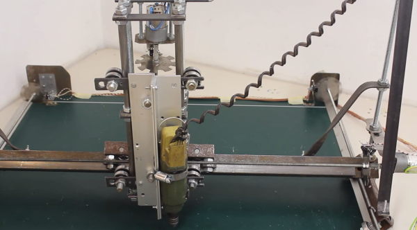
Home Made CNC Router Boasts Welded Steel Frame And Super Tidy Wire Management

[Cooperman] had been poking around the ‘net checking out DIY CNC machines for a while. He wanted to build one. During his search, he noticed that there was a common thread amongst homemade machines; they were usually made from parts that were on hand or easily obtainable. He had some parts kicking around and decided to hop on the band wagon and build a CNC Router. What sets [Cooperman]’s project apart from the rest is that he apparently had some really nice components available in his parts bin. The machine is nicknamed ‘Tweakie‘ because it will never really be finished, there’s always something to tweak to make it better.

The foundation for Tweakie is a welded frame made from 25mm steel square tubing. A keen observer may point out that welding a frame may cause some distortion and warping. [Cooperman] thought of that too so he attached aluminum spacers to the steel frame and lapped them flat. After that, fully supported THK linear bearings were attached to the now-straight spacer surface. Both the X and Y axes have ball-screws to minimize backlash and are powered by NEMA23 stepper motors. The Z axis uses 16mm un-supported rods with pillow block linear bearings. Unlike the X and Y, the Z axis uses a trapezoidal lead screw and bronze nut. [Cooperman] plans on replacing this with a ball-screw in the future but didn’t have one on hand at the time of assembly.

Mach3 is the software being used to control the CNC Router. It communicates via parallel port with a 3-axis StepMaster motor driver board that can handle providing 24vdc to the stepper motors. All of the electronics are mounted neatly in an electrical cabinet mounted on the back of the machine. Overall, this is a super sturdy and accurate machine build. [Cooperman] has successfully cut wood, plastic and even aluminum!

Simple Pen Plotter

Simple DIY Pen Plotter, Great First CNC Project

[Morten] has been busy recently making a pen plotter. It is a simple and elegant build that he completely designed from the ground up. There are no extra frivolous parts here. The frame is made from laser-cut plexiglass which makes fabrication easy if you have access to a laser cutter. Two NEMA17 motors are responsible for the machine’s movement. One moves the pen carriage back and forth by way of a belt. The other is connected by laser-cut gears to a roller bar, scavenged from an ink jet printer, that moves the paper media forward and aft underneath the pen.

The software chain used here is sort of uncommon compared to other inexpensive DIY CNC machines we see here on Hackaday. [Morten] creates his geometry with Rhino, then uses a plugin called Grasshopper to generate the g-code that controls the machine. That g-code is sent using gRemote to an Arduino flashed with the contraptor.org g-code interpreter. A RAMPS board takes the step and direction signals generated by the Arduino and moves the two stepper motors appropriately.

In typical open-supporting fashion, [Morten] has made his design files freely available for anyone to download. His plotter moves the pen side to side and the paper front to back in order to draw shapes but that’s not the only way a plotter can work. Check out this polar plotter and this one that hangs.

Check out the video after the break…

Continue reading “Simple DIY Pen Plotter, Great First CNC Project”

resourceful cnc router

Resourceful CNC Router Built From Hardware Store Parts

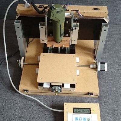
[siemen] has entered the wonderful world of Hobby CNC with his low-buck build of this gantry-style router. It embodies everything we here at HaD love: resourcefulness, perseverance and results. [siemen] has designed his frame using ideas he has found while surfing around the ‘net and is made entirely out of particle board. For linear movement, the Y and Z axes rely on ball bearing drawer slides while the X axis use a pipe and skate bearing arrangement. NEMA 17 stepper motors coupled to threaded rod move each axis.

The electronics are packaged in a nice little project box which houses an Arduino and 3 Sparkfun EasyStepper stepper motor drivers. [siemen] also cut a hole in the project box and installed a fan in order to keep those motor drivers cool. The Arduino is flashed with the CNC machine controller called GRBL. GRBL takes g-code sent from a PC to the Arduino and then in turn sends the required step and direction signals to the stepper motor drivers.

Overall, [siemen] did a great job with his first CNC project which came in at 200 Euro ($240). He’s currently working on version 2 and we are looking forward to covering it when it’s done. If you dig this project, you may also like this wooden wood router or this bolt-together one.

Continue reading “Resourceful CNC Router Built From Hardware Store Parts”

Peculiar Radial Mill From Car Parts

Whether 3D printer, lasercutter, or mill, most CNC machines use human-friendly, square-angle Cartesian geometry. This intriguing concept mill instead uses radial axes where motion is derived from scrap Chevy flywheels. It may look and feel weird at first, but it works – sort of.

Cartesian axes are intuitive. If you want to go to the right, increase X. If you want to go to away from you, increase Y. If you want to lift, increase Z. On a manual mill this is easy for making rectangles and blocks, or, with creative clamping, straight lines of any sort. But if you want to carve a circle? As we all learned on an Etch-A-Sketch, you increase your swearing and then throw it in the corner.

HAD - Radial Mill2[Jason] knew that with a CNC machine all geometry problems are reduced to math done by software. With two offset discs, any position is possible by rotating both the correct way. It may look odd that both plates drunkenly meander about just to draw a straight line but the computer is ambivalent. Software can be complicated without penalty and is free once written – more on that later. If a machine is physically simple then it can be built and repaired easily and cheaply. This design does away with almost all the familiar – and [Jason] argues complicated – components of normal hobby CNC machines. No slides, rails, carriages or belts here. His design uses only about a dozen parts.

Because automotive flywheels are made from cast iron the machine is rigid and naturally dampening. Sticking with the junkyard theme he pulled bearings from an F-450 truck, good for a few thousand pounds. Some steppers and a Raspberry Pi and he was done – well, sort of.

[Jason] let us know that his project has sat for long enough that he has become passionate about other things and decided to move on. He documented his progress and submitted the tip in hope to inspire someone else to continue the design further. Any type of CNC is possible, not just a mill. 3D printer perhaps?

Two big caveats: it needs a Z-axis (linear, probably standard) and there appears to be deeper-seated-than-expected G-code demands to chit-chat about rectangles and only rectangles. Nothing insurmountable, just nothing he has solved yet himself.

[Jason] said not to expect any further updates from him but he would love to see what the next person could do with it.

See the video after the break of the mill drawing our skull and wrenches logo, (soft of, without a Z-axis to lift).

Continue reading “Peculiar Radial Mill From Car Parts”

Flashing Chips With A CNC

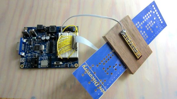
[Eberhard] needed to flash several hundred ATMegas for a project he was working on. This was a problem, but the task did have a few things going for it that made automation easy. The boards the ‘Megas were soldered to weren’t depanelized yet, and he had a neat and weird bed of nails programming connector. There was also a CNC machine close by. This sounds like the ideal situation for automation, and it turns out the setup was pretty easy.

The boards in question were for FPV/radio control telemetry adapter and thankfully the assembly house didn’t depanelize the 40 PCBs on each board before shipping them out. A very cool ATMega flashing tool handled the electrical connections between the computer and the microcontroller, but a real, live human being was still required to move this flashing tool from one chip to the next, upload the firmware, and repeat the process all over again.

The solution came by putting a few metal pins in the bed of a CNC mill, 3D print an adapter for the flashing tool, and writing a little code to move the flashing tool from one chip to the next. An extremely simple app takes care of moving the programmer to an unflashed chip, uploading the firmware, and continuing on to the next chip.

There’s still some work to be done that would basically tie together the Gcode and AVRdude commands into a single interface, but even now a complete panel of 40 PCBs can be programmed in a little over 10 minutes. You can check out a video of that below.

Continue reading “Flashing Chips With A CNC”