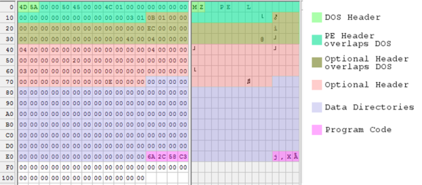
Programmers and software engineers will always use the latest development environments, the trendiest frameworks, and languages they learned only 21 days ago. What if this weren’t the case? What if developers put care into their craft and wrote programs with an old world charm? What if Windows executables were made with the same patience as artisanal firewood, or free range granola? [Steve] has done it. He’s forging a path into the wilds of truly hand crafted executables.
The simplest executable you could run on a Windows box is just a simple .COM file. This is an extremely simple file format that just contains code and data loaded into 0100h, and a jump to another point in the code. The DOS .EXE file format is slightly more complicated, but not by much. [Steve]’s goal was to build a proper Windows executable without a compiler, assembler, linker, or anything else.
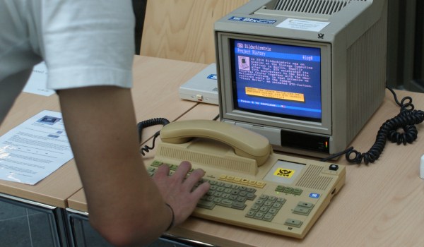
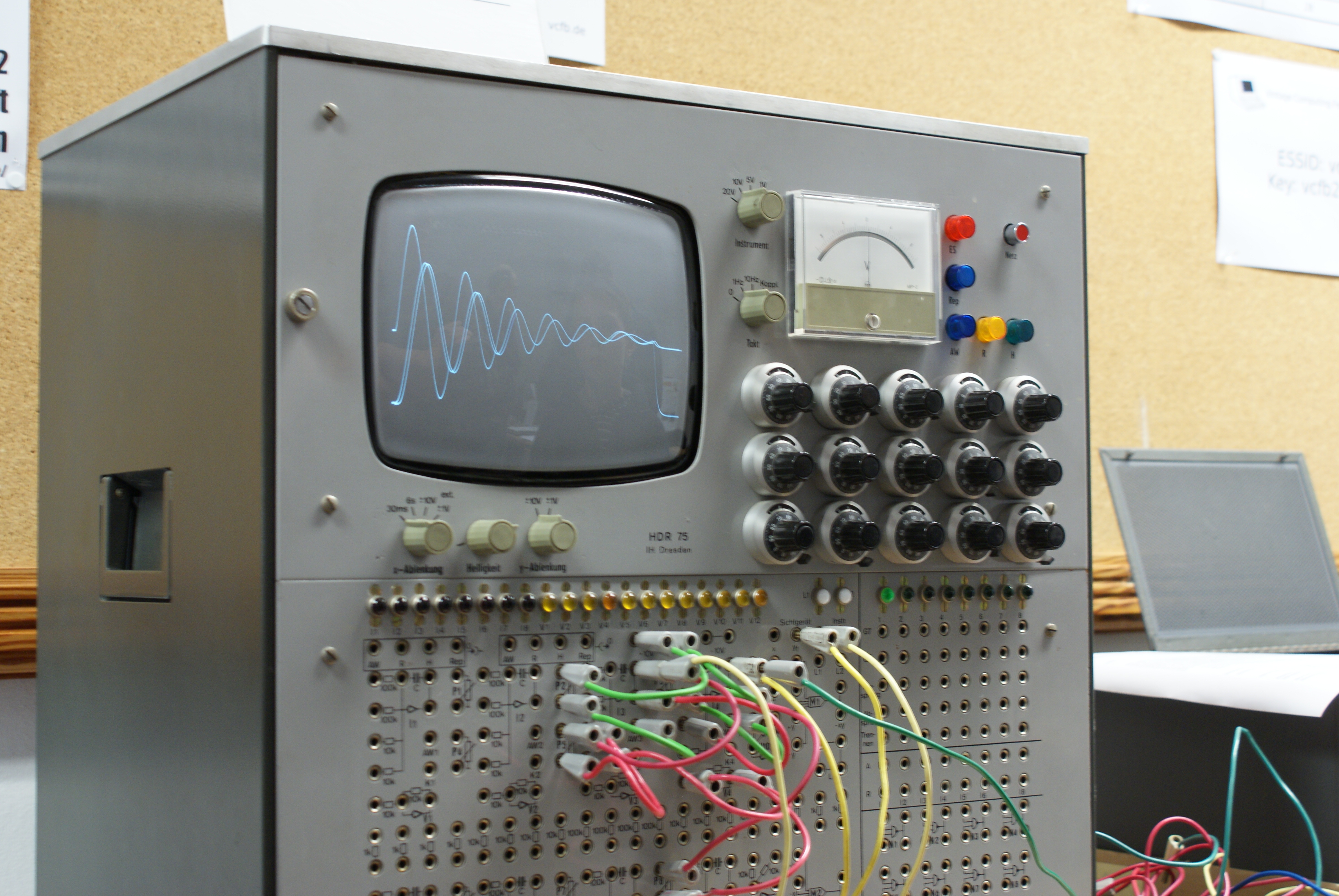
Berlin was a good city to be a geek in last weekend. Alongside the Berlin Maker Faire, there was the 2015 meeting of the Vintage Computing Festival: Berlin (VCFB). Each VCFB has a special theme, and this year it was analogue computers, but there was no lack of old computers large and small, teletext machines, vintage video game consoles, and general nerdy nostalgia.
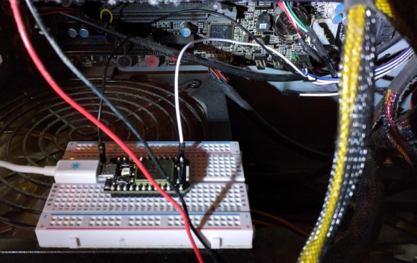
[Carter Yagemann] found himself in a bit of a pickle. He uses his computer mostly for gaming, but would like to access it remotely from time to time to do a littler server work on the side. The problem is gaming computers eat up a lot of electrons and he didn’t want to waste them by leaving it on all the time. The obvious solution was to use the Wake on Lan function. Unfortunately, his motherboard did not support this technology.
Like any good hacker would do, [Carter] used an IoT board to connect the power button of his PC to the internet. He achieved this goal with a Particle Core board. His motherboard was an ATX variety, so wiring up two of the IoT board’s I/O pins to the power on pins on the motherboard was a simple task accomplished with the help of an inline resistor.
This hack is so easy that it’s a great alternative to the blinky LED first program we all know so well. Want to get started in the hacking community? This is a great way to get going.
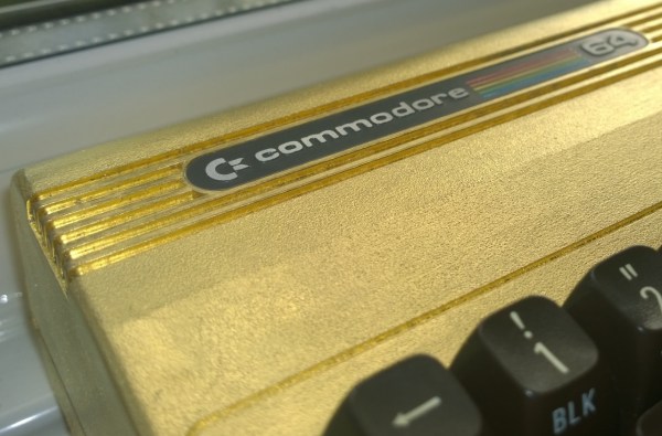
Alright, it’s not gold-plated, it’s gilded. For the uninitiated, gilding is the process of gluing gold powder or gold leaf to an object. Gold is amazingly ductile – a tiny nugget 5mm in diameter can be hammered into a sheet of gold leaf that can cover about a half a square meter. It’s extremely thin and delicate and has to be handled very gingerly, and the gilder’s craft is therefore very meticulous. For more on gilding, see this post on signmaking with gold leaf.
[thefuturewas8bit], who runs a vintage Commodore web store, did a great job gilding a C64 case, just because. The attention to detail is fantastic – notice that even the edges of the keyboard cutouts are gilded and burnished. A nice finishing touch is swapping out the stock red power LED for a yellow one – red simply clashes too much. Lest you think there’s nothing to learn from a purely aesthetic hack, [thefuturewas8bit] shares a great tip for removing the metal badges from a plastic case – spray them with freeze-spray from the back to pop off the glue. No need to dig at them with a screwdriver and gouge or bend them. Nice trick.
Any hack can earn extra points for style, and we think that gold works well on the C64. But if gold is a little too overstated for you, you can always try to score a colorful new injection-molded case for your vintage Commodore.
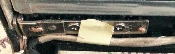
The weakest point in a laptop case may be the screen hinges, especially in heavily used machines. The mechanical stresses involved with opening a laptop can often break the thin plastic screw bosses and cause the threaded insert to pop out. What do you do? Get a hammer and some tacks of course!
[mightysinetheta]’s solution involves popping the bezel off the offending screen, then aligning the hinges in preparation for drilling holes though the computer’s plastic lid. Then he placed some short tacks though the holes and the hinges. Pressing the hinge down into the lid to ensure a tight fit, the hammer comes out to peen over the tip of the nail. Course that can be time consuming so just bending the tack over and flattening it down with the hammer works just as well.
With the hinge secured back into place his trusty laptop is back in service. The new additions on the back of the lid add a bit of a custom look that is purely functional.
One of the keys to nuclear fission is sustaining a chain reaction. A slow chain reaction can provide clean power for a city, and a fast one can be used to create a weapon that will obliterate a city. These days, kids can learn about Uranium and Plutonium in high school. But just a few generations ago, the idea of splitting the atom was just a lofty goal for the brightest physicists and mathematicians who gathered at Los Alamos National Laboratory under the Manhattan Project.
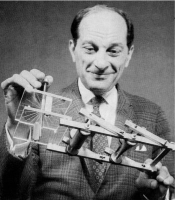
Decoding the mysteries of nuclear fission required a great deal of experimentation and calculations. One bright physicist in particular made great strides on both fronts. That man was [Enrico Fermi], one of the fathers of the atomic bomb. Perhaps his greatest contribution to moving the research beyond the Manhattan Project was creating a handheld analog computer to do the math for him. This computational marvel is known as the FERMIAC.
What is Fission?
Nuclear fission occurs when a nucleus is split into fragments, a process that unleashes a great deal of energy. As a handful of neutrons travel through a reactor pile or other fissionable material, a couple of outcomes are possible. Any one neutron collision might result in fission. This means there will be some number of new neutrons whose paths must be tracked. If fission does not occur, the neutrons may simply scatter about upon collision, which changes their speed and trajectory. Some of the neutrons might be absorbed by the material, and others will simply escape it. All of these possibilities depend on the makeup of the material being bombarded and the speed of the neutron.
Every event that happens to a neutron comprises its genealogical history. If this history is recorded and analyzed, a statistical picture starts to emerge that provides an accurate depiction of the fissility of a given material. [Fermi]’s computer facilitated the creation of such a picture by performing mathematical grunt work of testing different materials. It identified which materials were most likely to sustain a reaction.
Before he left Italy and the looming threat of fascism, [Fermi] led a group of young scientists in Rome called the Via Panisperna boys. This group, which included future Los Alamos physicist [Emilio Segrè], ran many experiments in neutron transport. Their research proved that slow neutrons are much better candidates for fission than fast neutrons.
During these experiments, [Fermi] ran through the periodic table, determined to artificially irradiate every element until he got lucky. He never published anything regarding his methods for calculating the outcomes of neutron collisions. But when he got to Los Alamos, [Fermi] found that [Stanislaw Ulam] had also concluded that the same type of repeated random sampling was the key to building an atomic weapon.
The Monte Carlo Method: Shall We Play a Game?
Monte Carlo method applied to approximating the value of π. by CaitlinJo
[Ulam], a Polish-born mathematician who came to the US in 1935, developed his opinion about random sampling due to an illness. While recuperating from encephalitis he played game after game of solitaire. One day, he wondered at the probability of winning any one hand as laid out and how best to calculate this probability. He believed that if he ran through enough games and kept track of the wins, the data would form a suitable and representative sample for modeling his chances of winning. Almost immediately, [Ulam] began to mentally apply this method to problems in physics, and proposed his ideas (PDF) to physicist and fellow mathematician [John von Neumann].
This top-secret method needed a code name. Another Los Alamos player, [Nick Metropolis] suggested ‘Monte Carlo’ in a nod to games of chance. He knew that [Ulam] had an uncle with a propensity for gambling who would often borrow money from relatives, saying that he just had to go to Monte Carlo. The game was on.
The Tricky Math of Fission
Determination of the elements most suitable for fission required a lot of calculations. Fission itself had already been achieved before the start of the Manhattan Project. But the goal at Los Alamos was a controlled, high-energy type of fission suitable for weaponization. The math of fission is complicated largely because of the sheer number of neutrons that must be tracked in order to determine the likelihood and speed of a chain reaction. There are so many variables involved that the task is monumental for a human mathematician.
[Stanislaw Ulam] and FERMIAC.
After [Ulam] and [von Neumann] had verified the legitimacy of the Monte Carlo method with regard to the creation of nuclear weaponry, they decided that these types of calculations would be a great job for ENIAC — a very early general purpose computer. This was a more intensive task than the one it was made to do: compute artillery firing tables all day and night. One problem was that the huge, lumbering machine was scheduled to be moved from Philadelphia to the Ballistics Research Lab in Maryland, which meant a long period of downtime.
While the boys at Los Alamos waited for ENIAC to be operational again, [Enrico Fermi] developed the idea forego ENIAC and create a small device that could run Monte Carlo simulations instead. He enlisted his colleague [Percy King] to build the machine. Their creation was built from joint Army-Navy cast off components, and in a nod to that great computer he dubbed it FERMIAC.
FERMIAC: Hacking Probabilities
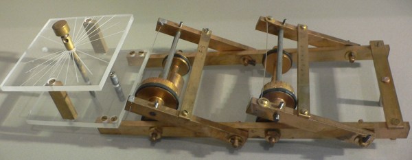
FERMIAC was created to alleviate the necessity of tedious calculations required by the study of neutron transport. This is something of an end-run around brute force. It’s made mostly of brass and resembles a trolley car. In order to use it, several adjustable drums are set using pseudorandom numbers. One of these numbers represents the material being traversed. A random choice is made between fast and slow neutrons. A second digit is chosen to represent the direction of neutron travel, and a third number indicates the distance traveled to the next collision.
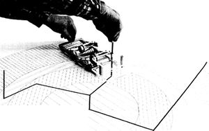
FERMIAC in action.
Once these settings are dialed in, the device is physically driven across a 2-D scale drawing of the nuclear reactor or materials being tested. As it goes along, it plots the paths of neutrons through various materials by marking a line on the drawing. Whenever a material boundary is crossed, the appropriate drum is adjusted to represent a new pseudorandom digit.
FERMIAC was only used for about two years before it was completely supplanted by ENIAC. But it was an excellent stopgap that allowed the Manhattan Project to not only continue unabated, but with rapid progress. FERMIAC is currently on display at the Bradbury Science Museum in Los Alamos, New Mexico alongside replicas of Fat Man and Little Boy, the weapons it helped bring to fruition. [Fermi]’s legacy is cemented as one of the fathers of the atomic bomb. But creating FERMIAC cements his legacy as a hacker, too.
After Los Alamos, [Stanislaw Ulam] would continue to make history in the field of nuclear physics. [Enrico Fermi] was opposed to participating in the creation of the exponentially more powerful hydrogen bomb, but [Ulam] accepted the challenge. He proved that Manhattan Project leader [Edward Teller]’s original design was unfeasible. The two men worked together and by 1951 had designed the Teller-Ulam method. This design became the basis for modern thermonuclear weaponry.
Today, the Monte Carlo method is used across many fields to describe systems through randomness and statistics. Many applications for this type of statistical modeling present themselves in fields where probabilities are concerned, like finance, risk assessment, and modeling the universe. Wherever the calculation of all possibilities isn’t feasible, the Monte Carlo method can usually be found.
UPDATE: Commentor [lwatchdr] pointed out that the use of the FERMIAC began after the Manhattan Project had officially ended in 1946. Although many of the same people were involved, this analog computer wasn’t put into use until about a year later.
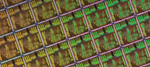
Moore’s Law states the number of transistors on an integrated circuit will double about every two years. This law, coined by Intel and Fairchild founder [Gordon Moore] has been a truism since it’s introduction in 1965. Since the introduction of the Intel 4004 in 1971, to the Pentiums of 1993, and the Skylake processors introduced last month, the law has mostly held true.
The law, however, promises exponential growth in linear time. This is a promise that is ultimately unsustainable. This is not an article that considers the future roadblocks that will end [Moore]’s observation, but an article that says the expectations of Moore’s Law have already ended. It ended quietly, sometime around 2005, and we will never again see the time when transistor density, or faster processors, more capable graphics cards, and higher density memories will double in capability biannually.