Oscilloscope Piano Tuning 101

fft on scope

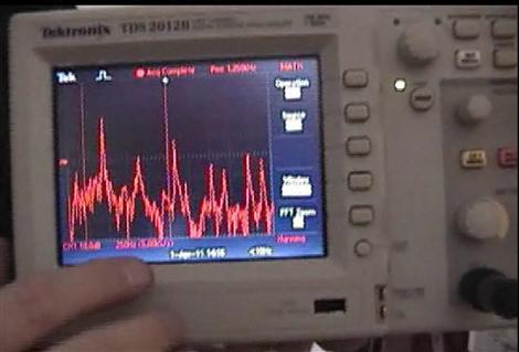
[Todd Harrison] recently wrote in to tip us off on his submission to the Tektronix oscilloscope contest – using a scope to tune a piano. In his video he demonstrates how a Fast Fourier Transform can be used to determine the fundamental frequency of the note being played. This is a quick and easy way to determine if that key is in tune, and if not, how far off it is from the desired frequency and in which direction.

He goes on to explain that a scope can only be used as a starting reference point since “mathematically correct” tuning on a piano doesn’t sound right to the human ear. It turns out that when struck, the stretched wires in the piano behave less than ideally. In the case of a piano, the overtones (the other peaks shown on the scope higher in frequency than the fundamental) are actually slightly sharper (higher in frequency) than the expected harmonic whole-number multiple of the fundamental frequency.  As a result, the frequency ranges of each octave must be “stretched” in order to accommodate this and sound correct when multiple notes are played together across octaves.

Typically, only the A4 key is actually tuned to its correct frequency of 440Hz and all of the other keys are manually tuned off of this baseline. The amount of necessary stretch applied to each octave increases as you get further away from this initial reference point in either direction and is unique to each and every individual instrument – thus there is no universal device capable of perfect tuning. Although [Todd] admits that he won’t attempt to tune the entire piano himself using this technique, he finds it a convenient way to keep the most heavily played center sections of the piano closer to true between professional tunings.

If you have any interesting or unique uses for your Techtronix scope, you can enter the contest here. Just don’t forget to tip us off too!  Thanks [Todd]!

Analog Scope Stands In To For Laser Light Show

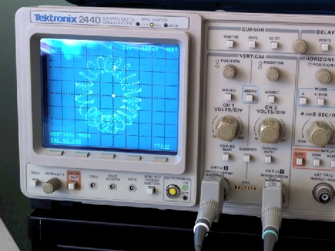
[Joey] likes to dabble in laser projection, building his own hardware and writing the software that drives it. One way that he tests his setup is by replacing the laser assembly with an analog oscilloscope. This allows him to ensure that the driver board is receiving data from the software, and translating it into the correct electrical signals to drive the motors controlling the mirrored redirection of the laser beam.

In the video linked above [Joey] walks us through this process. It starts by connecting scope probes to the digital-analog-converter card that outputs image data for the projector. From there the XY mode is used to map the two channels perpendicular to each other; the motors that these signals are meant to control have mirrors that also move perpendicular to one another. After adjusting the scale and the timebase you will see the pattern the laser dot is meant to trace.

[Joey] entered this in a Tectronix contest. There’s plenty of other interesting entries to browse though. If have an entry that you’d like to see featured, or if you come across any other interesting stuff, don’t forget to tip us off.

Analog Robot Navigates Around The Workshop With Ease

556_wall_following_robot

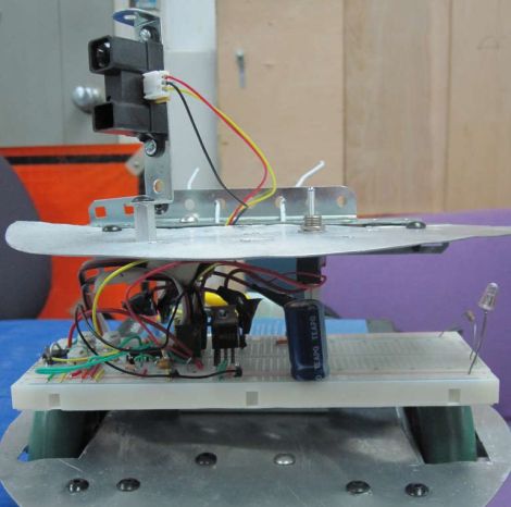
Many of the robots we feature here are driven by some sort of microcontroller, whether it be an Arduino, Launchpad, Picaxe, etc. Rarely do we see a robot however, using analog circuits to perform higher-level functions typically relegated to those more complex controllers. Instructables user [hasn0life] built such a robot recently, which he entered into a contest at his college. After hearing about the 555 design contest from a friend, he tweaked his project and created a wall-following robot using a 556 timer.

The robot is fairly simple when you take a close look, though that does not take away from the elegance of his design. A single IR sensor is used to detect objects in the robot’s periphery, guiding the robot along. When the robot gets too close to a wall, one wheel reverses, pulling the robot away. Once the robot has moved a sufficient distance, the other wheel is reversed in order to straighten out the robot. Then, both wheels work in concert to get the robot moving forward.

Take a look at the video below to watch the robot navigate its way around his workshop, and if you are interested in learning more about analog robotics, check out this post from a few days back.

Continue reading “Analog Robot Navigates Around The Workshop With Ease”

Pint-sized Nixie Display Fits Neatly In Your Pocket

[Brett] has had Nixie tubes on the brain ever since being introduced to them by a good friend of his. He decided that building a Nixie-based key chain would be the best way to familiarize himself with the technology, while also giving him a project to enter in the 555 Design Contest. He dug up the smallest Nixie tube he could find that displayed digits, and got down to business.

The biggest obstacle he ran into was figuring out how he would provide the high voltage required to light the Nixie tube. He eventually built a transformer circuit driven by a 555 timer, using a small 12v battery as his power source. Once everything was up and running on a breadboard, he designed and etched some PCBs, then soldered everything together.

The end result is a nifty little key chain that flashes the number 5 when a button is pressed – pretty appropriate for the 555 contest. It’s a great looking project, though we’re still not 100% sure what we think about a naked high voltage circuit residing in our pocket.

Keep reading for a pair of videos documenting the key chain’s construction and operation.

Continue reading “Pint-sized Nixie Display Fits Neatly In Your Pocket”

Endless Fun With LED Dominoes

le_dominoux

Toppling dominoes is great fun for about 30 seconds at a time, when you are not busy setting them up for another run. [Randy] thought it was about time they got an electronic makeover to allow for constant, immediate gratification. Armed with a few simple electronic components, he has created Le Dominoux.

These LED-based electronic dominoes are actually quite simple to build. Each basic Le Dominoux is constructed on a small square of protoboard and consists of either a photo cell or phototransistor, a 555 timer, and an LED, all powered by a coin cell battery. The 555 timer, which is configured as a one-shot, is triggered when the photosensitive component on the back side of the domino is exposed to a bright enough light. The LED on the front end of the domino is then illuminated one time. This process is the electronic equivalent of a single domino toppling over.

He has constructed several variants of the Le Dominoux to act as flashing triggers, for outputting sound, as well as for turning tight corners. These variants allow the dominoes to be configured in many different ways, creating self-sustaining light shows. If anyone is looking for a fun project to introduce kids to electronics, this would definitely be it. Stick around to see a video of Le Dominoux in action – we bet you can’t stop watching it.

This is of course [Randy’s] entry in the 555 Design Contest, which ends tonight at midnight EST.

[Thanks Jeri]

Continue reading “Endless Fun With LED Dominoes”

Bluetooth-enabled Talking Chicken

bluetooth_chicken

[Jeri Ellsworth] sent us a video walkthrough of a hack she did a few years ago using a toy chicken with a motor operated mouth. She wired up a Bluetooth headset’s audio output to a LM386 audio amplifier, which drives the speaker she added to the chicken. The output of the audio amplifier was also connected to a 555 timer in bistable mode to activate the motorized mouth. The motor simply opens the mouth when activated, allowing the built-in spring to snap it shut when the 555 is reset.

Obviously Jeri didn’t send us an old project just for kicks, she wanted to remind all of our readers that the 555 Design Contest comes to a close tomorrow night, March 1st at 11:59 EST. If you haven’t submitted an entry yet, get something started while there is still time!

Keep reading to see Jeri give a quick video overview of her talking Bluetooth chicken.

Continue reading “Bluetooth-enabled Talking Chicken”

Fun Slide Whistle Synth Toy

slide_synth

[Dino] recently sent us some info on his latest project, a 555 timer-based slider synthesizer. The synth was built to emulate the sound made by playing a slide whistle, and also as an entry into the 555 Design Contest, which is quickly coming to a close. If you’re not familiar with a slide whistle, just spend a few minutes on YouTube looking for clips of Sideshow Bob – it’s ok, we’ll wait.

The circuit is pretty simple, though the implementation is quite clever. While traditional slide whistles require the user to blow in one end, this electronic version operates using a LED and photo cell. When the main switch is closed, the 555 timer is activated, and a tone is produced. The pitch of the tone is controlled by the LED as it slides in and out of the tube. The more light that hits the photo cell, the higher the pitch, and vice versa.

Continue reading to see a quick demonstration of [Dino’s] slide synth, and be sure to check out his other 555 contest entry we featured a short while back.

Continue reading “Fun Slide Whistle Synth Toy”