[Glen]’s project sounds perfectly straightforward: have a big industrial-style push button act as a one-key USB keyboard. He could have hacked something together in any number of ways, but instead he decided to create a truly elegant solution. His custom PCB mates to the factory parts perfectly, and the USB cable between the button and the computer even fits through the button enclosure’s lead hole.
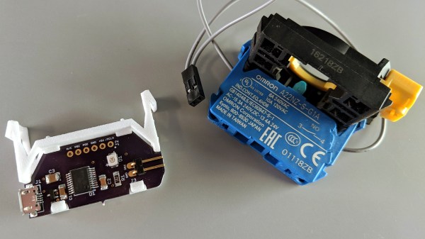
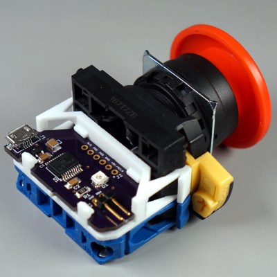 It turns out that industrial push buttons have standardized components which can be assembled in an almost LEGO-like manner, with components mixed and matched to provide different switch actions, light indicators, and things of that nature. [Glen] decided to leverage this feature to make his custom PCB (the same design used in his one-key keyboard project) fit just like a factory component. With a 3D printed adapter, the PCB locks in just like any other component, and even lines up with the lead hole in the button’s enclosure for easy connecting of the USB cable.
What does [Glen] use the big button for? Currently he has two applications: one provides a simple, one-button screen lock on a Linux box running a virtual machine at his place of work. It first disengages the keyboard capture of the virtual machine, then engages the screen lock on the host. The other inserts a poop emoji into Microsoft documents. Code and PCB design files for [Glen]’s small keyboards are available on GitHub.