If you’re not familiar with the 555 timer, suffice it to say that this versatile integrated circuit is probably the most successful ever designed, and has been used in countless designs, many of which fall very far afield from the original intent. From its introduction, the legendary 555 has found favor both with professional designers and hobbyists, and continues to be used in designs from both camps. New versions of the IC are still being cranked out, and discrete versions are built for fun, a temptation I just couldn’t resist after starting this article.
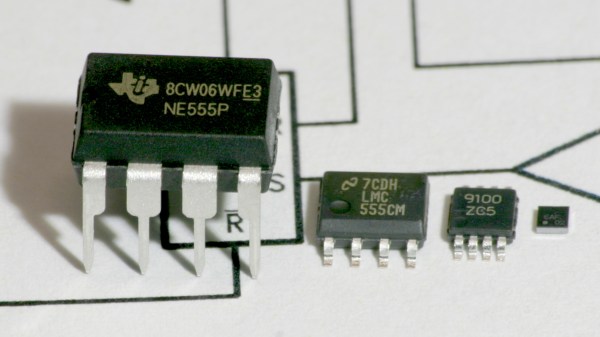
If you think all 555s are the same, think again. Today, a number of manufacturers continue to produce the 555 in the original bipolar formulation as well as lower-power CMOS. While the metal can version is no longer available, the DIP-8 is still around, as are new surface-mount packages all the way down to the chip-scale. Some vendors have also started making simplified variants to reduce the pinout. Finally, you can assemble your own version from a few parts if you need something the commercial offerings won’t do, or just want a fun weekend project. In my case, I came up with what is probably the fastest 555-alike around, although I spared little expense in doing so.
Follow along for a tour of the current state of the 555, and maybe get inspired to design something entirely new with this most versatile of parts.
Continue reading “Making The World’s Fastest 555 Timer, Or Using A Modern IC Version”


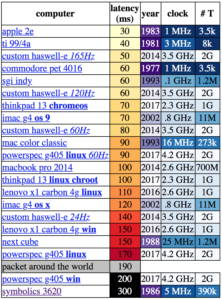 Let’s be clear about what “latency” means in this context. [danluu] was checking the time between a user input and some response on screen. For desktop systems he measured a keystroke, for mobile devices scrolling a browser. If you’re here on Hackaday (or maybe at a