Entries keep ticking in for the One Hertz Challenge, some more practical than others. [Pierre-Loup M.]’s One Hertz Sculpture has no pretensions of being anything but pretty, but we can absolutely respect the artistic impulse behind it.
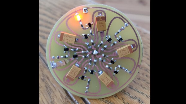
The sculpture is a free-form circuit inside of a picture frame. There are 9 LEDs in a ring with a few other components to produce a reverse-chase effect (one going dark at a time) taking about 1 second to circle the sculpture. As far as free-form circuit art goes, it’s handsomely done, but as this is Hackaday it’s probably the electronics, rather that the aesthetics that are of interest.
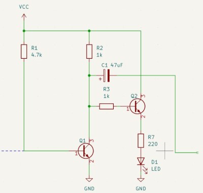
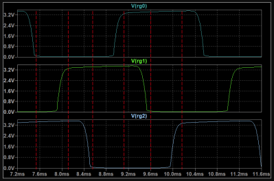
The circuit is an example of a ring oscillator: a cascading chain of NOT gates, endlessly feeding into and inverting one

another. The NOT gates are implemented in resistor-transistor logic with 2N3904 NPN transistors, nine in total. Of course the inverter delay of this sort of handmade logic gate is far too fast for an aesthetically pleasing (or visible) chase, so some extra circuitry is needed to slow down the oscillations to something less than the 5 MHz it would naturally do. This is affected by pairing every transistor with an RC oscillator. Ideally the RC oscillator would have a 0.111..s period (1/9th of a second), but a few things got in the way of that. The RC oscillator isn’t oscillating in a vacuum, and interactions with the rest of the circuit have it running just a little bit fast. That’s really of no matter; a simple oscillator circuit like this wasn’t going to be a shoe in for the accuracy-based Time Lords category of this contest. As a sculpture and not a clock, you’re not going to notice it isn’t running at exactly 1Hz. (Though a ring-oscillator based clock would be a sight indeed.)
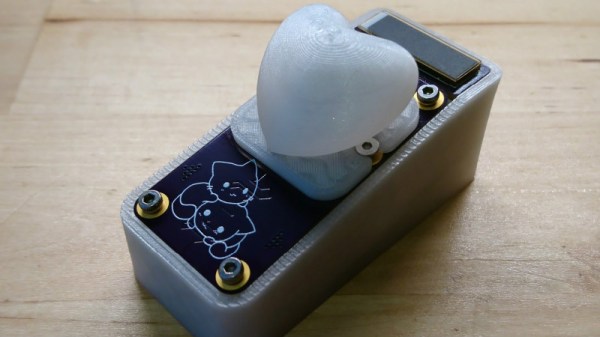
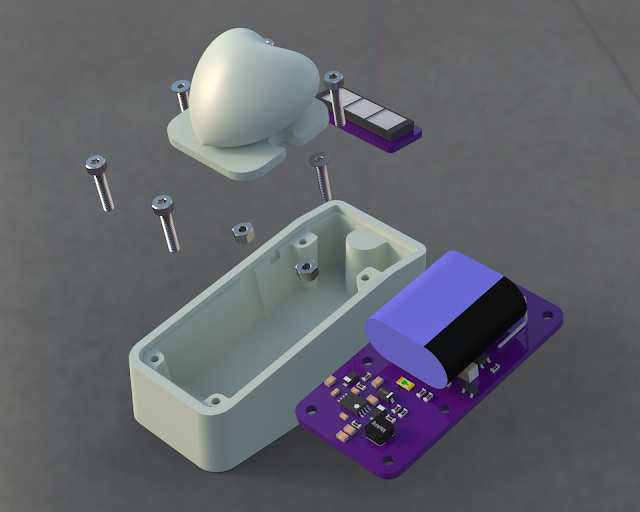
We’ve seen ring oscillators before, including inside the venerable 8087 coprocessor and this delightfully romantic beating-heart gift, but this is the first one that seems to have entered the One Hertz Challenge.
If you have a hankering for hertz, the contest is still open, but you’d better get ticking! The contest closes August 19th.