Custom Split-Flap Display Is A Unique Way To Show The Weather

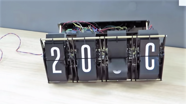
There’s little doubt about the charms of a split-flap display. Watching a display build up a clear, legible message by flipping cards can be mesmerizing, whether on a retro clock radio from the 70s or as part of a big arrival and departure display at an airport or train station. But a weather station with a split-flap display? That’s something you don’t see often.

We usually see projects using split-flap units harvested from some kind of commercial display, but [gabbapeople] decided to go custom and build these displays from the ground up. The frame and mechanicals for each display are made from laser-cut acrylic, as are the flip-card halves. Each cell can display a full alphanumeric character set on 36 cards, with each display driven by its own stepper. An Arduino fetches current conditions from a weather API and translates the description of the weather into a four-character code. The codes shown in the video below seem a little cryptic, but the abbreviation list posted with the project makes things a bit clearer. Bonus points if you can figure out what “HMOO” is without looking at the list.

We like the look and feel of this, but we wonder if split-flap icons might be a neat way to display weather too. It seems like it would be easy enough to do with [gabbapeople]’s detailed instructions. Or you could always look at one of the many other custom split-flap displays we’ve featured for more inspiration.

Continue reading “Custom Split-Flap Display Is A Unique Way To Show The Weather”

PC In An SNES Case Is A Weirdly Perfect Fit

For better or for worse, a considerable number of the projects we’ve seen here at Hackaday can be accurately summarized as: “Raspberry Pi put into something.” Which is hardly a surprise, the Pi is so tiny that it perfectly lends itself to getting grafted into unsuspecting pieces of consumer tech. But we see far fewer projects that manage to do the same trick with proper x86 PC hardware, but that’s not much of a surprise either given how much larger a motherboard and its components are.

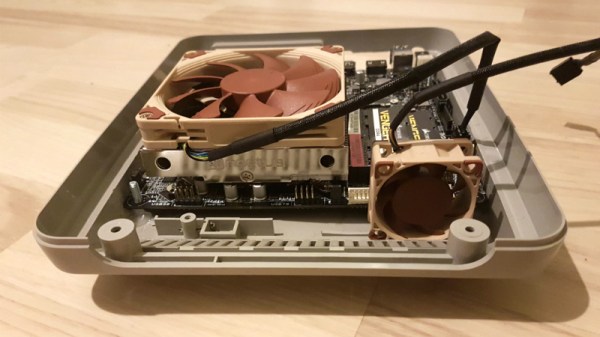
So this PC built into a Super Nintendo case by [NoshBar] is something of a double rarity. Not only does it ditch the plodding Raspberry Pi for a Mini-ITX Intel i5 computer, but it manages to fit it all in so effortlessly that you might think the PAL SNES case was designed by a time traveler for this express purpose. The original power switch and status LED are functional, and you can even pop open the cart slot for some additional airflow.

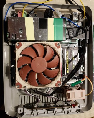
[NoshBar] started by grinding off all the protruding bits on the inside of the SNES case with a Dremel, and then pushed some bolts through the bottom to serve as mounting posts for the ASUS H110T motherboard. With a low profile Noctua CPU cooler mounted on top, it fits perfectly within the console’s case. There was even enough room inside to add in a modified laptop charger to serve as the power supply.

To round out the build, [NoshBar] managed to get the original power slider on the top of the console to turn the PC on and off by gluing a spring-loaded button onto the side of the CPU cooler. In another fantastic stroke of luck, it lined up almost perfectly with where the power switch was on the original SNES board. Finally, the controller ports have been wired up as USB, complete with an adapter dongle.

[NoshBar] tells us the inspiration for sending this one in was the Xbox-turned-PC we recently covered, which readers might recall fought back quite a bit harder during its conversion.

8087's -5V bias charge pump circuit

How The 8087 Coprocessor Got Its Bias

Most of us have been there. You build a device but realize you need two or more voltages. You could hook up multiple power supplies but that can be inconvenient and just not elegant. Alternatively, you can do something in the device itself to create the extra voltages starting with just one. When [Ken Shirriff] decapped an 8087 coprocessor to begin exploring it, he found it had that very problem. It needed: +5 V, a ground, and an additional -5 V.

His exploration starts with a smoking gun. After decapping the chip and counting out all the bond wires going to the various pads, he saw there was one too many. It wasn’t hard to see that the extra wire went to the chip’s substrate itself. This was for providing a negative bias to the substrate, something done in some high-performance chips to get increased speed, a more predictable transistor threshold voltage, and to reduce leakage current. Examining where the bond wire went to in the circuitry he found the two charge pump circuits shown in the banner image. Those worked in alternating fashion to supply a -5 V bias to the substrate, or rather around -3 V when you take into account voltage drops. Of course, he also explains the circuits and dives in deeper, including showing how the oscillations are provided to make the charge pumps work.

If this is anything like [Ken’s] previous explorations, it’ll be the first of a series of posts exploring the 8087. At least that’s what we hope given how he’d previously delighted us with a reverse engineering of the 76477 sound effects chip used in Space Invaders and then went deeper to talk about integrated injection logic (I2L) as used in parts of the chip.

When Every Last Nanoamp Matters

You can get electricity from just about anything. That old crystal radio kit you built as a kid taught you that, but how about doing something a little more interesting than listening to the local AM station with an earpiece connected to a radiator? That’s what the Electron Bucket is aiming to do. It’s a power harvesting device that grabs electricity from just about anywhere, whether it’s a piece of aluminum foil or a bunch of LEDs.

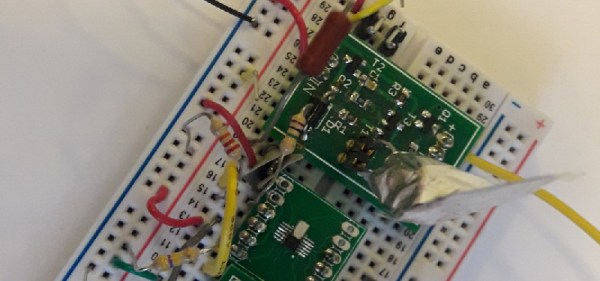
The basic idea behind the Electron Bucket is to harvest ambient radio waves just like your old crystal radio kit. There’s a voltage doubler, a rectifier, and as a slight twist, a power management circuit that would normally be found in battery-powered electronics.

Of course, this circuit can do more than harvesting electricity from ambient radio waves. By connecting a bunch of LEDs together, it’s possible to send a few Bluetooth packets around. This is pretty impressive — the circuit is using LEDs as solar cells, which normally produce about 50nA of current at 0.5V in direct sunlight. By connecting 12 LEDs in parallel and series, it manages to harvest just enough energy to run a small wireless module. That’s impressive, and an interesting entry to the Power Harvesting Challenge in this year’s Hackaday Prize.

An Achievable Underwater Camera

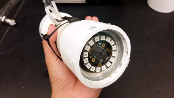
We are surrounded by sensors for all forms of environmental measurement, and a casual browse through an electronics catalogue can see an experimenter tooled up with the whole array for a relatively small outlay. When the environment in question is not the still air of your bench but the turbulence, sand, grit, and mud of a sea floor, that pile of sensors becomes rather useless. [Ellie T] has been addressing this problem as part of the study of hypoxia in marine life, and part of her solution is to create an underwater camera by encasing a Raspberry Pi Zero W and camera in a sturdy enclosure made from PVC pipe. She’s called the project LoBSTAS, which stands for Low-cost Benthic Sensing Trap-Attached System.

The housing is simple enough, the PVC has a transparent acrylic disk mounted in a pipe coupler at one end, with the seal being provided at the other by an expansion plug. A neopixel ring is mounted in the clear end, with the Pi camera mounted in its centre. Meanwhile the Pi itself occupies the body of the unit, with power coming from a USB battery bank. The camera isn’t the only sensor on this build though, and Atlas Scientific oxygen sensor  completes the package and is mounted in a hole drilled in the expansion plug and sealed with silicone sealant.

Underwater cameras seem to have featured more in the earlier years of Hackaday’s existence, but that’s not to say matters underwater haven’t been on the agenda. The 2017 Hackaday Prize was carried off by the Open Source Underwater Glider.

Bench Power Supply Packs A Lot Into A DIN-Rail Package

We’re not sure why we’ve got a thing for DIN-rail mounted projects, but we do. Perhaps it’s because we’ve seen so many cool industrial control cabinets, or maybe the forced neatness of DIN-mounted components resonates on some deep level. Whatever it is, if it’s DIN-rail mounted, chances are good that we’ll like it.

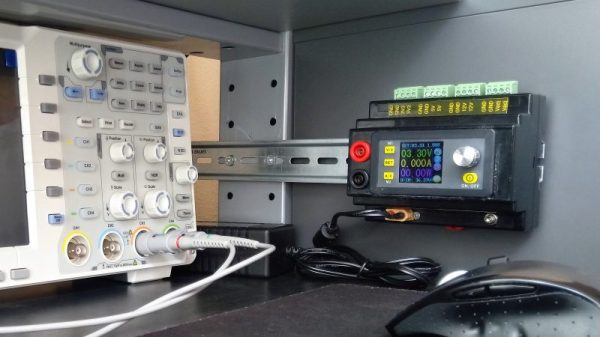
Take this DIN-mounted bench power supply, for instance. On the face of it, [TD-er]’s project is yet another bench supply built around those ubiquitous DPS switching power supply modules, the ones with the colorful displays. Simply throwing one of those in a DIN-mount enclosure isn’t much to write home about, but there’s more to this project than that. [TD-er] needed some fixed voltages in addition to the adjustable output, so a multi-voltage DC-DC converter board was included inside the case as well. The supply has 3.3, 5, and 12 volt fixed outputs along with the adjustable supply, and thanks to an enclosed Bluetooth module, the whole thing can be controlled from his phone. Plus it fits nicely in a compact work area, which is a nice feature.

We haven’t seen a lot of DIN-rail love around these pages — just this recent rotary phase converter with very tidy DIN-mounted controls. That’s a shame, we’d love to see more.

JB Weld – Strong Enough To Repair A Connecting Rod?

JB Weld is a particularly popular brand of epoxy, and features in many legends. “My cousin’s neighbour’s dog trainer’s grandpa once repaired a Sherman tank barrel in France with that stuff!” they’ll say. Thankfully, with the advent of new media, there’s a wealth of content out there of people putting these wild and interesting claims to the test. As the venerable Grace Hopper once said, “One accurate measurement is worth a thousand expert opinions“, so it’s great to see these experiments happening.

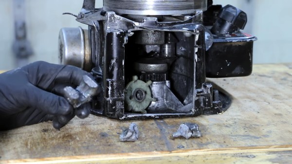
[Project Farm] is one of them, this time attempting to repair a connecting rod in a small engine with the sticky stuff. The connecting rod under test is from a typical Briggs and Stratton engine, and is very much the worse for wear, having broken into approximately 5 pieces. First, the pieces are cleaned with a solvent and allowed to properly dry, before they’re reassembled piece by piece with lashings of two-part epoxy. Proper technique is used, with the epoxy being given plenty of time to cure.

The result? Sadly, poor — the rod disintegrates in mere seconds, completely unable to hold together despite the JB Weld’s best efforts. It’s a fantastic material, yes – but it can’t do everything. Perhaps it could be used to cast a cylinder head instead?

Continue reading “JB Weld – Strong Enough To Repair A Connecting Rod?”