Adding Remote Control To An Old Stereo

Sometimes, the best hifi gear is the gear you’ve already got. This is particularly the case in the cassette world, as high quality decks are long out of production. [Nick] liked his current rig, but wanted to be able to use it with a remote from across the room. Naturally, he set to hacking the feature in.

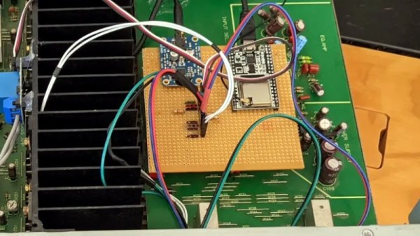
The cassette deck in question, a Yamaha K-220, was old enough to lack a remote, but thankfully new enough to use a computer-controlled tape transport. This meant that the basic features of play, stop, rewind and fast forward can all be controlled with simple digital buttons rather than mechanical ones. This made it easy to interface an ATmega328P to the stereo’s original circuitry. Digital IO pins are hooked up to the buttons, held as high-impedance inputs most of the time, only toggling to ground when necessary to trigger a button press. It was then a simple job to hook up an IR receiver to the chip and program it with some Arduino libraries to work with a typical stereo remote control [Nick] had laying around.

It’s a tidy build, and with more cool cassette releases coming out every year, we’re sure [Nick]’s going to put some miles on the setup. If you find IR too cumbersome though, you can go a step further and replace it with a web app instead. If you’ve been tinkering with similar things in your own workshop, be sure to drop us a line!

Listening To Long Forgotten Voices: An Optical Audio Decoder For 16 Mm Film

Like many of us, [Emily] found herself on COVID-19 lockdown over the summer. To make the most of her time in isolation, she put together an optical audio decoder for old 16 mm film, built using modern components and a bit of 3D printing.

It all started with a broken 16 mm projector that [Emily] got from a friend. After repairing and testing the projector with a roll of film bought at a flea market, she discovered that the film contained an audio track that her projector couldn’t play. The audio track is encoded as a translucent strip with varying width, and when a mask with a narrow slit is placed over the top it modulates the amount of light that can pass through to a light sensor connected to speakers via an amplifier.

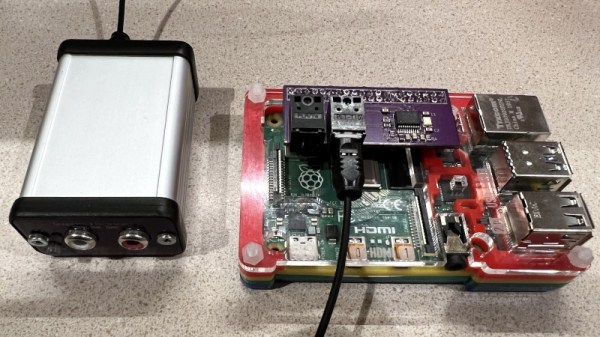
[Emily] used a pair of razor blades mounted to a 3D printed bracket to create the mask, and a TI OPT101 light sensor together with a light source to decode the optical signal. She tried to use a photoresistor and a discrete photodiode, but neither had the required sensitivity. She built a frame with adjustable positions for an idler pulley and the optical reader unit, an electronics box on one end for the electronic components, and another pulley attached to a stepper motor to cycle a short loop of the film.

Most of the projects we see involving film these days are for creating digital copies. You can digitize your old 35 mm photo film using a Raspberry Pi, some Lego pieces, and a DSLR camera, or do the same for 8 mm film with a 3D printed rig. Continue reading “Listening To Long Forgotten Voices: An Optical Audio Decoder For 16 Mm Film”

Building Distributed Mode Loudspeakers With Plywood

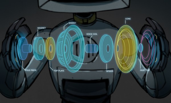
Distributed-mode loudspeakers work rather differently from the typical drivers used in 99% of applications. Instead of using piston-like motion to create sound waves, they instead rely on exciting an entire panel to vibrate and thus produce sound. [JGJMatt] decided to build a pair of bookshelf-sized units, with great results.

The build begins with a pair of 44mm DML exciters, readily available online. These had to be modified to remove their stock metal mounting plates that degraded the sound output in early tests. Instead, 3D printed pieces were used to mount the exciters to the 3mm plywood boards, which were lasercut to act as the main DML panels. Additionally, whizzer cones were fitted to the panels in an effort to further boost the high frequency response of the speakers. The speaker stands are assembled out of more 3D printed pieces and aluminium rods, giving a clean, modern look to the final product.

The performance of the speakers is admirable based on the test video, though [JGJMatt] notes that they should be paired with a subwoofer in use as the DML units do not readily produce frequencies below 100Hz. We’ve seen similar builds before on a larger scale, too. Video after the break.

Continue reading “Building Distributed Mode Loudspeakers With Plywood”

Auto Tuning For A Vintage Stereo

In 1984 there weren’t many ways to listen to high-quality music, so an FM tuner was an essential part of any home hi-fi system. The Pioneer TX-950 picked up by [The Curious Lorenz] would have been someone’s pride and joy, with its then-cutting-edge microprocessor control, digital PLL tuning, and seven-segment displays. Astoundingly it doesn’t have an auto-tuning function though, so some work to implement the feature using an ATtiny85 was called for.

A modern FM tuner would be quite likely to use an all-in-one tuner chip using SDR technology under the hood, but this device from another era appears to be a very conventional analog tuner to which the PLL and microprocessor have been grafted. There are simple “Up” and “Down” buttons and a “Station tuned” light. One might imagine that given these the original processor could have done autotune. At least the original designers were kind enough to provide the ATtiny with the interfaces it needs. Pressing either button causes it to keep strobing its line until the “Station tuned” line goes high, at which point it stops. It’s an extremely simple yet effective upgrade, and since the ATtiny is so small it’s easily placed on top of the original PCB. The result is an ultra-modern tuner from 1984, that’s just that little bit more modern than it used to be.

If you don’t have a vintage FM radio, you can always build its modern equivalent.

An Epic Quest For A Motorized Volume Knob

[Haris Andrianakis] likes his Logitech Z623 sound system. He likes it a lot. Which is why he was willing to hack in his own remote volume control rather than just get a new pair of speakers. But he certainly didn’t make things easy on himself. Rather than trying to tap into the electronics, he decided to take the long way around and motorize the volume knob.

The belt drive looked great, but didn’t work.

The idea seemed simple enough. Just drill a hole through the PCB behind the knob’s potentiometer, attach some kind of extension to the axle, and turn it with a small servo. Modifying the PCB and potentiometer went well enough, but the trouble came when [Haris] actually tried to turn the thing.

Attaching the servo directly to the axle worked, but it made turning the knob by hand extremely difficult. His next idea was to add a small belt into the mix so there would be some slip in the system. But after designing a 3D printed servo mount and turning custom pulleys on the lathe, it ended up having too much slip, and the knob didn’t always move when the servo turned.

He then swapped out the servo for a small stepper motor. The motor was easy enough to spin when powered down, but didn’t have quite enough torque to turn the knob. He tried with a larger stepper motor that he salvaged from an old printer, but since he could only run it at half the recommended 24 VDC, it too had a tendency to skip steps.

After experimenting with some 3D printed reduction gears, [Haris] finally stumbled upon the 28BYJ-48. This small stepper with an integrated gearbox proved to be the perfect solution, as it had enough muscle to turn the knob while at the same time not restricting its movement when powered down. The rest of the project was relatively easy; with a DRV8825, an ESP8266, and an IR receiver, he’s able to spin the stepper with his TV’s remote. A simple web page running on the ESP8266 even allows him to control volume over the network with his smartphone. Based on similar projects we’ve seen, he could probably add support for HDMI CEC as well.

[Haris] says you shouldn’t follow his example, but we’re not so sure. He kept going when others would have given up, and the engineering and thought that went into each attempt is certainly commendable. Even if he hadn’t ultimately gotten this project working, we’d still say it was a valiant hack worthy of praise.

Digispark Spoofs IR To Get Speakers Under Control

The Microlab 6C are a pretty nice pair of speakers, but [Michał Słomkowski] wasn’t too thrilled with the 8 watts they consume when on standby. The easy fix is to just unplug them when they aren’t in use, but unfortunately the digital controls on the front panel mean he’s got to turn them on, select the correct input, and turn the volume up to the appropriate level every time they’re plugged back in. Surely there must be a better way.

His solution was to use a Digispark to fire off the appropriate IR remote codes so they’d automatically be put back into a usable configuration. But rather than putting an IR LED on one of the GPIO pins, he simply spliced it into the wire leading back from the speaker’s IR receiver. All his code needs to do is generate the appropriate pulses on the line, and the speaker’s electronics think its a signal coming in from the remote.

Distinctive patterns on the IR sensor wires.

Power for the Digispark is pulled from the speaker itself, so it turns on once [Michał] plugs them back in. The code waits five seconds to make sure the hardware has had time to start up, then proceeds with the “Power On”, “Change Input”, and “Volume Up” commands with a few seconds in between each for good measure.

Not only was it easier to skip the IR and inject the signals directly, but it also made for a cleaner installation. Since the microcontroller doesn’t need line of sight to the IR receiver, [Michał] was able to hide it inside the speaker’s enclosure. From the outside, the modification is completely invisible.

We’ve seen similar code injection tricks used before, and it’s definitely one of those techniques you should file away mentally for future reference. Even though more and more modern devices are embracing WiFi and Bluetooth control, the old school IR remote doesn’t seem like it’s going away anytime soon.

Projecting Halloween Peril

Every holiday has a few, dedicated individuals committed to “going all out.” Whether they’re trying to show up the neighbors, love the look, or just want to put a smile on the faces of those passing by; the results are often spectacular. A recent trend in decorations has been away from analog lights and ornaments and towards digital light shows via a projector. [Georgia Clegg] and [Luma Bakery] have written up a fantastic guide detailing the involved process of house projection for those feeling the holiday spirit.

There is more to the effect than simply pointing a projector at a home and running a video clip. The good displays make use of the geometry of the home and the various depths of the walls don’t distort the picture. The house itself is mapped into the image being displayed.

There are generally two approaches to mapping: point of view mapping and neutral/orthographic mapping. The first is just setting the projector in a fixed position and designing the graphics in such a way that they will look correct. The downside is that if there are multiple projectors, each projector will need to be separately designed for and they cannot be moved or adjusted. The second maps the house in an actual 3d sense and figures out how to display the content according to the viewpoint that the projector is currently at. This means you can create one source content and simply export it for the various projectors.

As you can imagine, the second is much more involved and this is where [Georgia Clegg] has stepped in. There’s a whole series that covers creating your house in MeshRoom, cleaning it up in Blender, creating the videos in After Effects, and setting up your projector to keep it running through the season.

We’ve seen other amazing projector mapping displays with lasers here at Hackaday. Now you can make one yourself. Just don’t get bogged down refurbishing your vector projector along the way.
Continue reading “Projecting Halloween Peril”