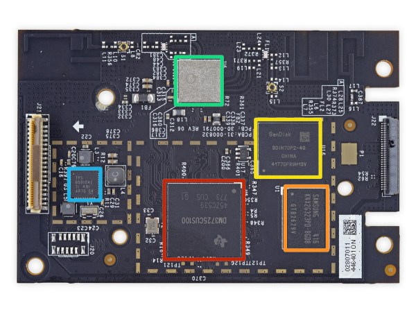
Unless you’ve been living under a case of 1 farad capacitors, you’ve heard of the Amazon Echo. Roughly the size of two cans of beans, the Echo packs quite a punch for such a small package. It’s powered by a Texas Instrument DM3725 processor riding on 256 megs of RAM and 4 gigs of SanDisk iNAND ultra flash memory. Qualcomm Atheros takes care of the WiFi and Bluetooth, and various TI chips take care of the audio codecs and amplifiers.
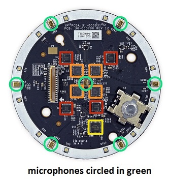
What’s unique about Echo is its amazing voice recognition. While the “brains” of the Echo exist somewhere on the Internets, the hardware for this circuitry is straight forward. Seven, yes seven microphones are positioned around the top of the device. They feed into four Texas Instrument 92dB SNR low-power stereo ADCs. The hardware and software make for a very capable voice recognition that works from anywhere in the room. For the output sound, two speakers are utilized – a woofer and a tweeter. They’re both powered via a TI 15 watts class D amplifier. Check out this full tear down for more details of the hardware.
Now that we have a good idea of the hardware, we have to accept the bad news that this is a closed source device. While we’ve seen other hacks where people poll the to-do list through the unofficial API, it still leaves a lot to be desired. For instance, the wake word, or the word which signals the Echo to start listening to commands, is either “Alexa” or “Amazon”. There is no other way to change this, even though it should be easily doable in the software. It should be obvious that people will want to call it “Computer” or “Jarvis”. But do not fret my hacker friends, for I have good news!
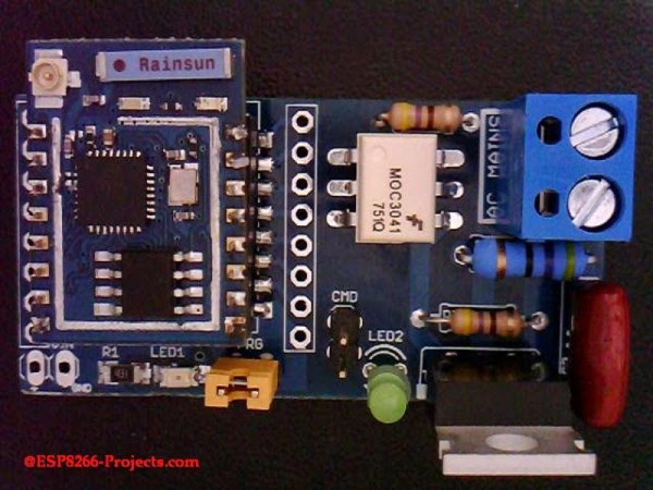
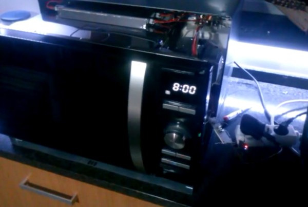
It appears that Amazon sees (or had seen all along) that home automation is the future of the Echo. They now officially support Philips Hue and Belkin WeMo gadgets. The Belkin WeMo, which is no stranger to the hacker’s workbench, has a good handle on home automation already, making the ability to control things in your house with the Echo tantalizingly close. See the video below where I test it out. Now, if you’re not excited yet, you haven’t heard of the WeMo Maker, a device which they claim will let you “Control nearly any low-voltage electronics device“. While the WeMo Maker is not supported as of yet, it surely will be in the near future.
We know it sucks that all of this is closed source. But it sure is cool! So here’s the question: Is the Echo the future of home automation? Sure, it has its obvious flaws, and one would think home automation is not exactly Amazon’s most direct business model (they just want you to buy stuff). However, it works very well as a home automation core. Possibility better than anything out there right now – both closed and open source.
Do you think Amazon would ever open the door to letting the Echo run open source modules which allow the community to add control of just about any wireless devices? Do you think that doing so would crown Amazon the king of home automation in the years to come?
Continue reading “Ask Hackaday: Is Amazon Echo The Future Of Home Automation?” →

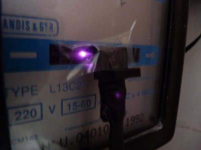 So he figured out a way to extract data from the existing meters. For the Electricity meter, he thought of using current clamps, but punted that idea considering them to be suited more for instantaneous readings and prone for significant drift when measuring cumulative consumption. Eventually, he hit upon a pretty neat hack. He took a slot type opto coupler, cut it in half, and used it as a retro-reflective sensor that detected the black band on the spinning disk of the old electro-mechanical meter. Each turn of the disk corresponds to 4 Watt-hours. A little computation, and he’s able to deduce Watt-hours and Amps used. The sensor is hooked up to an Arduino Pro-mini which then sends the data via a nRF24L01+ module to the main circuit located inside his house. The electronics are housed in a small enclosure, and the opto-sensor looks just taped to the meter. He has a nice tip on aligning the infra-red opto-sensor – use a camera to check it (a phone camera can work well).


