A Brief History Of The Crazy Old 7-Segment Display

How old is the seven-segment display? Surely it is a product of the 1970s. After all, calculators started showing up, and the height of junior high humor was plugging 7734 into your calculator and showing it to someone upside down. Of course, for it to go mainstream, maybe they really originated in the 1960s, but no earlier than that, right? Actually, no. Sure, the LED seven-segment display had to wait for LEDs. But the actual idea is much older than that.

The concept of building numbers from a small set of reusable segments predates LED displays by decades. In fact, the basic idea appears in patents from the early 1900s and may have roots in even older mechanical signs and printing techniques.

The history isn’t entirely straightforward. Unlike vacuum tubes or transistors, segmented displays evolved gradually through a series of practical ideas rather than one defining invention.

Blacking out the Eight

While looking into the history of segmented displays, I was reminded of something I’d seen years ago in retail stores: reusable price tags printed with rows of eights.

Rather than printing every possible price, the clerk simply used a marker to black out portions of each figure, transforming an 8 into whatever digit was needed. Cover a few strokes, and the eight becomes a three. Remove a different set, and it becomes a zero or a five. It was, in essence, a manual segmented display.

Finding the exact origin of these price tags is akin to finding out where Romans bought sponges. They were inexpensive commercial supplies, not the sort of products that historians carefully documented. My recollection is from the middle of the twentieth century, but the underlying concept is almost certainly older.

Continue reading “A Brief History Of The Crazy Old 7-Segment Display”

A Light-Up Map Of Monaco

If you want to get around Monaco, a map — digital or otherwise — is probably the best way to navigate. But if you just want to appreciate the city’s form in a more artistic way, you might enjoy [Terence Grover’s] latest project—a backlit topographic map of the unique principality.

The touch mode allows one to draw patterns across the map.

The project started with a QGIS mesh of Monaco, with the data fed through the Open-Meteo elevation API, which takes into account building heights. This was used as the basis for the heights of 179 pieces of 20 mm x 20 mm acrylic. These were assembled into a laser cut steel base, and were sanded on all sides but the base in order to allow them to diffuse light more effectively.

Strips of CS8812 LEDs are used to light the plastic towers, driven by a pair of Adafruit Feather RP2040 Scorpio boards. They’re fed pixel data from a Raspberry Pi 5, which runs a Flask panel accessed over an iPad. This allows control over the LED map display, showing things like civic data, highlighted events, and weather. There’s even a touch-sensitive mode that lets one paint fun patterns across the representation of the city.

We love a good artistic map, particularly when they’re full of LEDs and represent useful information.

Continue reading “A Light-Up Map Of Monaco”

Lightcomposer

LightComposer – Reach Out And Touch Your Lighting

While there is a time and place for wirelessly controlled devices, sometimes you want something you can just reach out and touch to interact with, no apps to install or devices to configure. In this case [John] wanted a lamp that was just that. Drawing inspiration from the rotary phone, he created the LightComposer.

This small lamp, just a bit smaller than a hockey puck, uses a 3D printed enclosure and a straightforward PCB. It’s a very accessible project to recreate. The 3D prints are well thought out including a TPU ring on the bottom to keep the lamp from sliding around. The light source comes from 32 SK6812 LEDs, which are very similar to NeoPixels. An ATmega328P microcontroller powers the project and can easily be programmed using the Arduino IDE. A rotary encoder in the center, coupled to the top diffuser, lets you control LED brightness and color by turning it. The firmware also includes some fun hidden light-effect modes.

Head over to [John]’s site for all the files needed to make your own LightComposer, or links to buy a premade one. What devices have you made that use a straightforward physical user interface in lieu of an app? Be sure to check some of the other lamp builds we’ve featured before.

A Diffraction Grating Makes This Clock Readable

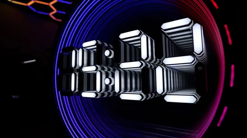
We’ve seen just about every possible way to make a clock here at Hackaday over the years. So it’s rare to have a first, but here we are with [Twisted & Tinned], who’s made a novel clock with a diffraction grating.

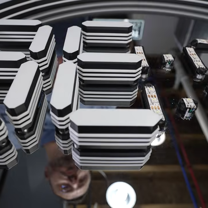
The display of the clock looks for all the world like a jumble of LEDs, that is, until you place the grating in front of it. Those LEDs are addressable multi-color parts, and each digit is generated at a different color all on top of each other. The grating splits out these colors, resulting in a magical set of floating LED figures.

Behind those LEDs is a Pi Pico, but that’s just one of many microcontrollers that could have powered this project. It’s the use of the diffraction grating in a novel way with those LEDs that makes the difference, and we rather like it. He’s also managed to get the grating pattern in the 3D printed surround for a shimmering look, by printing directly onto a diffraction grating sheet. That in particular is a technique we’ve looked at before in detail.

Continue reading “A Diffraction Grating Makes This Clock Readable”

Transforming Lamp Built With LED Filaments

[Nick Electronics] had an idea to build a stylish lamp that could transform its shape while lit. This goal was achieved beautifully with the aid of many, many filament LEDs.

If you’re unfamiliar with filament LEDs, they’re basically thin plastic filaments stuffed with lots of individual LEDs that are very close together. This effectively creates a continuous, flexible, glowing string that can be used for all sorts of creative purposes.

[Nick] packed the lights into an interlocking stack of PCBs that make up the lamp’s structure. Each PCB layer hosts four filaments mounted around the outer edge, and has a pin that locks into a groove in the next layer to allow them to tug each other around as they turn. The PCBs rotate around a central shaft, with power passed from one to the other via interlinking wires. Drive is via a stepper motor on top of the lamp, controlled by an A4988 driver. There’s also an ATmega48 microcontroller onboard, which is the brains of the operation. A DC-DC converter onboard steps up the 5 V input voltage from USB-C to 10 volts for the stepper motor.

It’s neat to watch the lamp in action, glowing and slowly shifting in patterns as the layers catch and rotate in and out of alignment. We’ve seen interesting builds in this vein before, like this fantastic origami lamp from a few years ago.

Continue reading “Transforming Lamp Built With LED Filaments”

Building Festival Badges That Sync Themselves Up

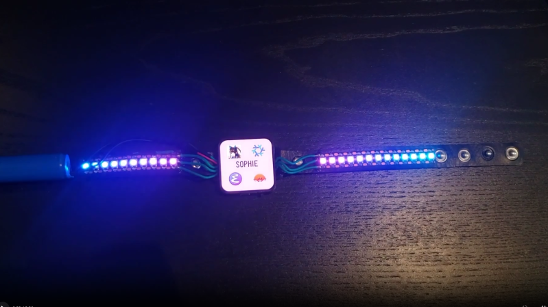
Lots of music events these days hand out various glowing tchotchkes that flash and sync up with the performance. [Tony Goacher] has whipped up his own badges that can do just that, all without needing any sort of pairing or infrastructure to speak of.

The CrowdClock badges each feature a ring of 16 addressable RGB LEDs. Running the LEDs is an ESP32 microcontroller, which has lots of neat wireless capability baked in from the factory. [Tony] decided to leverage the ESP-NOW wireless communication protocol to enable each badge to broadcast its current local clock tick. Each device also listens out for clock ticks from other badges in the area, and updates its current clock tick value if it receives a higher one from another badge. This behaviour allows a bunch of badges within radio range to all sync up automatically in short order, and then run their LED sequences in sync. There’s no need for a master designation or anything, the devices just all sync to whichever badge has the highest clock value and go from there.

It’s a really neat way to create propagating self-syncing behaviour in distributed wireless nodes. Files are on Github for those curious to learn more. Meanwhile, if you’ve ever wondered how those concert wristbands work, we’ve looked at that too. Video after the break.

Continue reading “Building Festival Badges That Sync Themselves Up”

Building A Working Replica Of The Chernobyl Power Plant’s SKALA Display

In a recent video by the [Chornobyl Family] it’s shown how they made the SKALA status display which was featured at the recent 40-year memorial exhibition of the Chornobyl Nuclear Power Plant (ChNPP) #4 reactor accident, along with the RBMK reactor control panel replica and SKALA console which they had made previously.

Detail of the SKALA display. (Credit: Chornobyl Family, YouTube)

We previously covered this SKALA control system of the ChNPP’s RBMK reactors, as well as its 1990s modernization. This SKALA status display is one of the original elements of the control room, providing a status overview of the entire control system at a glance, including its processors and peripheral devices.

The replica uses similar looking components, with a metal casing and LED lighting that invokes the aesthetics of the original electroluminescent mnemonic panels. Overall the goal was to keep the appearance as close to the original as possible — they even had operators of the ChNPP reactors look over the panel and give it their stamp of approval.

Some of the components like the error indicators had to be 3D printed, while the metal case was cut out of sheet metal. There’s also a very big speaker for the alarm, at the top right of the panel. Along with the LEDs for the electroluminescent-style indicators this meant a lot of addressable LEDs and a lot of wiring.

The full build plans are available via the [Chornobyl Family] Patreon, if you feel like building up your own RBMK-style reactor control room.

Continue reading “Building A Working Replica Of The Chernobyl Power Plant’s SKALA Display”