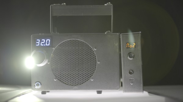
LED Matrix Failure And Vindication

If necessity is the mother of invention, what’s failure the mother of? Improvement? Anyway, [prpplague]’s second version of his roll-up 70×30 RGB LED display looks a lot better and more reliable than the first, and that’s precisely due to “failing”.

Sometimes you design the hardware around the software, and sometimes vice-versa. It’s all about the balance of pain. [prpplague] initially wired the strips together in a consistently left-to-right raster arrangement to make the coding easier, but this means long wires on the backside of the fabric returning from the right side back to the start again at the left. These long wires snagged on stuff, and pulled the solder connections apart.

600px-Dotstar-adapter-solder3The fix? Alternate rows of left-to-right with right-to-left to minimize wiring and make nice, robust connectors for the ends, and a much more elegant implementation at the expense of more complicated software to drive the device. (Alternating rows have to be flipped horizontally, so this means custom driver routines.)

The second gremlin was that the interfacing board that [prpplague] was using didn’t have enough current sourcing capability on the SPI lines, and he discovered that he couldn’t communicate reliably with the strings if the first pixel was more than 24″ of wire away from the board. Once the signal got to the first pixel, though, everything was fine. [prpplague] figured out that the RGB LEDs themselves had more drive capability than the SPI source.

The solution? Add a single pixel at the front of the chain to buffer the SPI lines and serve as a bonus status indicator. Cute.

We’d hardly call these “fails”, but rather “learning experiences”. Anyway, here’s two design “mistakes” that we won’t make when making a roll-up flexible pixel display. Thanks [prpplague].

neopixals

Seven Segment Clock Made From Scratch

[David Hopkins] built a seven segment clock, but not in a way you would think.  Typically, if one wants to make something like this, one would start off with some seven segment LEDs. [David] wanted to kick it up a notch and use RGB LEDs to get access to the wide array of different colors, but found off the shelf assemblies cost prohibitive. So, he did what any good hacker would do. He made his own.

clockThe easy part consists of Neopixels, an Arduino Nano and a DS3231 Real Time Clock. The hard part consists of Plasticard and a polymorph diffuser. Plasticard also goes by the name of Polystyrene and comes in sheets. [David] describes Polymorph as a type of moldable nylon that softens with heat, with a working temperature low enough that boiling water will suffice.

He was able to cut out the individual segments to make an impressive looking desk clock.

Hackaday Prize Entry: Lighting The Way For Walkers

Chances are, you probably know someone who uses a walker to assist in their mobility. Ever wonder about how they could be made better? When [Alan McFarland] noticed his friend using his iPhone as a light to walk down a hallway — with only one hand on his walker — he realized something could easily be done to make the walker more functional. His own light bar.

Sure you could get a flashlight, zip tie it to the walker, or maybe a bike light with a dedicated mount — but [Alan] wanted it to be a bit more elegant; and functional. With this in mind, he attached an LED light strip to the lower frame of the walker to help illuminate the path ahead. A button is wired up to the handle for easy access, and he’s even using a PIC12F1501 microcontroller to give it some logic — it’ll turn off by itself, fading out, giving the person a chance to sit down before the lights go out.

The thing we like about this project is he programmed it using the PICBASIC PRO compiler — the same compiler that [Alan] himself used nearly 20 years ago programming the Borg suits and spacesuit lighting on Star Trek: First Contact — how’s that for a random trivia fact!

The 2015 Hackaday Prize is sponsored by:

Bed Lights Keeps You From Stubbing Your Toe When Nature Calls

While out shopping for bed’s with his better half, [Shane] tried out one of the more expensive, all “bells and whistles” included models. While the aforementioned featurees were impressive, one stood out: motion controlled underlighting for when you had to get up in the middle of the night.

bed-underlighting-thumbKnowing that this feature would be easy to replicate [Shane] went about making his own version. Using PCV pipe to make the framework for the LED’s a 9 volt DC power supply, and a list of electronic components all that was left to figure out was the motion controls.

PIR motion sensors  are the natural choice and its simple enough to hook them up to the micro of your choice and bang out some code. It’s just as simple to hard wire them into a circuit skipping the added cost of the micro and complexity of the software.

The two PIR sensor outputs are wired though a diode OR gate, to a potentiometer to control sensitivity, and then to a pair of NPN transistors to ultimately control power to the LED strips. Now they have motion controlled night lights for their bed when nature calls in the middle of the night.

Jellyfish skirt

Jellyfish Inspired LED Skirt For Burning Man

[Lumilectric] is getting ready for Burning Man and made herself this fantastic fiber optic LED skirt.

She’s always been fascinated by fiber optics and the effect they create, so she wanted to try using them in a project, and this was just the ticket. The tricky part was figuring out how best to couple cheap fiber optic strands off eBay with a strip of RGB LEDs.

In the end she figured out a way to make rudimentary fiber optic coupling joints using vinyl tubing. She managed to fit 17 strands of 0.5mm diameter fiber into a 6mm diameter vinyl tube. To improve light transfer when it’s all together, you can gently melt the ends of the fiber optics together to glaze the plastic into a single clear surface — don’t melt the vinyl though!

Continue reading “Jellyfish Inspired LED Skirt For Burning Man”

Aurora Painting

“Arduino Borealis” Combines LEDs And Paint

[Stef Cohen] decided to combine three different artistic mediums for her latest project. Those are painting, electronics, and software. The end goal was to recreate the aurora borealis, also known as the northern lights, in a painting.

The first step was to make the painting. [Stef] began with a shadow box. A shadow box is sort of like a picture frame that is extra deep. A snowy scene was painted directly onto the front side of the glass plate of the shadow box using acrylic paint. [Stef] painted the white, snowy ground along with some pine trees. The sky was left unpainted, in order to allow light to shine through from inside of the shadow box. A sheet of vellum paper was fixed to the inside of the glass pane. This serves to diffuse the light from the LEDs that would eventually be placed inside the box.

Next it was time to install the electronics. [Stef] used an off-the-shelf RGB LED matrix from Adafruit. The matrix is configured with 16 rows of 32 LEDs each. This was controlled with an Arduino Uno. The LED matrix was mounted inside the shadow box, behind the vellum paper. The Arduino code was easily written using Adafruit’s RGB Matrix Panel library.

To get the aurora effect just right, [Stef] used a clever trick. She took real world photographs of the aurora and pixelated them using Photoshop. She could then sample the color of each pixel to ensure that each LED was the appropriate color. Various functions from the Adafruit library were used to digitally paint the aurora into the LED matrix. Some subtle animations were also included to give it an extra kick.

LED Organ Chimes Its Light Pipes

Light pipes are a pretty tricky feature to pull off. If the generic set on Digikey doesn’t meet your size and shape constraints, you’ll need to either find a vendor who can fabricate a specific shape for you or redesign that feature altogether. [Folker’s] LED Organ does an excellent job in piping light out from the source, and he does so in a way that’s reproducible with just a couple hours at the hand tools and a couple minutes on a laser cutter.

Hidden inside the base is a cluster of hardware that orchestrates the outer piece. 24 RGB LEDs are broken out into a ring and hidden in the base. [Folker’s] design enables control of the ring through either the LED player or LED Stamp with pattern-generation made possible by the free software, Jinx!

These days, exposed LEDs are ubiquitous enough among DIY electronics to almost be considered a hallmark of the DIY-enthusiast. Sure, “getting the project off the ground” is a great mindset to adopt when trying out some new firmware or components, but it can often leads us to a project’s finish with most of the wiring still exposed. While we’re certainly not offended by exposed LEDs, the task of concealing the shape of these components while also achieving the desired lighting effects is a challenge and rare sight to see. Our hats are off to the execution of this visual symphony.

Continue reading “LED Organ Chimes Its Light Pipes”