LED Matrix Displays Get New Look Thanks To SMD Stencils

Even if surface-mount skills aren’t in your repertoire, chances are pretty good that most of us are at least familiar with SMD stencils. These paper-thin laser-cut steel sheets are a handy way to apply a schmear of solder paste to the pads of a PCB before component placement and reflowing. But are stencils good for anything else?

It turns out they are, if you’ve got some plain old 8×8 LED matrix displays you want to jazz up a bit. In this case, [upir]’s displays were of the square pixel type, but this trick would work just as well for a matrix with circular elements. Most of the video below is a master class in Adobe Illustrator, which [upir] used to generate the artwork for his stencils. There are a lot of great tips here that make creating one simple shape and copying it over the whole array with the proper spacing a lot easier. He also details panelizing multiple stencils, as well as the workflow from Illustrator to manufacturing.

When lined up properly over the face of the LED matrix, the stencils have quite an effect. We really liked the narrow vertical bars, which make the LED display look a bit like a VFD. And just because [upir] chose to use the same simple shape over all the LEDs in a matrix doesn’t mean that there aren’t other options. We can see how you might use the same technique to create different icons or even alphanumeric characters to create custom LED displays. The possibilities are pretty much limited to your imagination.

This isn’t the first time we’ve seen [upir] teaching old displays new tricks.

Continue reading “LED Matrix Displays Get New Look Thanks To SMD Stencils”

Smooth Animations, Slick Bar Graphs, But No Custom Characters On This 16×2 OLED

Sometimes, finding new ways to use old hardware requires awesome feats of reverse engineering, software sleight of hand, and a healthy dose of good fortune. Other times, though, it’s just as simple as reading the data sheet and paying attention to details.

Not that we’re knocking [upir]’s accomplishment with these tricked-out 16×2 OLED displays. Far from it, in fact — the smoothly animated bar graph displays alphanumerics look fantastic. What’s cool about this is that he accomplished all this without resorting to custom characters. We’ve seen him use this approach before; this time around, the hack involves carefully shopping for a 16×2 OLED display with the right driver chip — a US2066 chip. You’ll still need a few tricks to get things working, like extra pull-up resistors to get the I2C display talking to an Arduino, plus a little luck that you got a display with the right character ROM.

Once all that is taken care of, getting the display to do what you want is mainly a matter of coding. In the video below, [upir] does a great job of walking through the finer points, and the results look great. The bar graphs in particular look fantastic, with silky-smooth animations.

Continue reading “Smooth Animations, Slick Bar Graphs, But No Custom Characters On This 16×2 OLED”

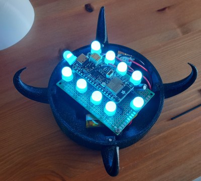
3D printed Hagrid's lantern with a magic wand

Micro:bit Brings 3D Printed Magic Lanterns To Life

[Elenavercher] loves engaging her primary school students, inspiring their imagination as well as teaching them the design thinking process. She has found that the very accessible rapid prototyping culture of 3D printing, micro:bit, and the like are perfect for teaching her students problem-solving and teamwork, and is always coming up with new lessons that will catch their attention. That brings us to her latest design, an interactive lantern and wand, which you could say is of the wizarding variety.

The lantern and the wand each have an integrated micro:bit serving as their brains. When the user shakes the wand, releasing a spell, the micro:bit in the wand, sends a user-defined number to the micro:bit in the lantern. The lantern has NeoPixels built-in, which then turn on, illuminating the lantern. When the user presses a button on the micro:bit instead of shaking it, the wand sends a signal to the lantern that tells it to “turn off.” Pretty simple, right?

The design itself is something any seasoned hacker could recreate; however, the magic in this build is how [Elenavercher] beautifully engages her elementary-aged students in the engineering design process. She starts off by encouraging her students to prototype the lantern and wand using paper which is a very inexpensive way to help them visualize the final product before investing too much time into the 3D design, a critical engineering design step — prototype fast and cheap with whatever you have on hand.

She then helps them design the lantern and wand in Tinkercad, a very beginner-friendly, yet increasingly capable CAD program. We really appreciate her detailed steps for the design as well as for navigating Tinkercad, both of which will help teach any tiny tikes in your life how to recreate the design. What’s really handy about Tinkercad is you can do mechanical CAD as well as write code for the micro:bit all within the same program. But [Elenavercher] also provides the final .hex file if you’d rather just get the build up and running.

Continue reading “Micro:bit Brings 3D Printed Magic Lanterns To Life”

IOT Message Board Puts Fourteen-Segment Displays To Work

We’re not sure, but the number of recognizable alphanumeric characters that a seven-segment display can manage seems to have more to do with human pattern recognition than engineering. It takes some imagination, and perhaps a little squinting, to discern some characters, though. Arguably better is the fourteen-segment display, which has been pressed into service in this just-for-funsies IOT message board.

As [Steve] tells the story, this is one of those “boredom-buster” projects that start with a look through the junk bin to see what presents itself. In his case, some fourteen-segment common-cathode LEDs presented themselves, and the result was a simple but fun build. [Steve] used some clever methods to get the display stuffed onto two protoboards, including mounting the current-limiting resistors cordwood-style between the boards. A Raspberry Pi drives the display through a very neatly routed ribbon cable, and the whole thing lives in a tidy wooden box.

The IOT part of the build allows the display to show messages entered on [Steve]’s web page, with a webcam live stream to close the loop. Strangely, the display seems stuck on the “HI HACKADAY!” we entered as a test after [Steve] tipped us off, so we’re not sure if we busted it or what. Apologies if we did, [Steve]. And by the way, if your cats are named [Nibble] and [Pixel], well done!

No matter what you do with them, multi-segment displays are pretty cool. But if you think they’re something new, you’ve got another think coming.

Three Way LED Bulb Gives Up Its Secrets

You’ve probably seen three-way bulbs. You know, the ones that can go dim or bright with each turn of a switch. [Brian Dipert] wondered how the LED version of these works, and now that he tore one apart, you can find out, too. The old light bulbs were easy to figure out. They had two filaments, one brighter than the other. Switching on the first filament provided some light, and the second gave off more light. The final position lit both filaments at once for an even brighter light.

LED or filament, three-way bulbs have a special base. While a normal Edison-base bulb has the threaded part as the neutral and a center contact for the live wire, a three-way bulb has an extra hot contact ring between the threaded part and the center contact. Obviously, a compatible LED bulb will need this same interface, but will work differently inside.

Inside the LED, [Brian] found two rings of LEDs that took the place of the filaments. He was able to identify all the ICs and devices on the board except one, an MT7712S. If you can read Mandarin, we think this is the datasheet for it.

We weren’t sure what [Brian] would find inside. After all, you could just sense which contacts had voltage and dim the LEDs using PWM. It probably wouldn’t take any less circuitry. LED lighting is everywhere these days, and maybe they don’t all work the same, but you have to admit, using two strings of LEDs is reasonably faithful to the old-fashioned bulbs.

Sometimes LED bulbs are different depending on where you buy them. We were promised LED bulbs would never burn out. Of course, they do, but you can usually scrounge some LEDs from them.

A Hacker’s Introduction To DIY Light Guide Plates

Last year, I found myself compelled to make a scaled-down replica of the iconic test chamber signs from the video game Portal. If you’ve played the game, you’ll remember these signs as the illuminated monoliths that postmarked the start of every test chamber. In hyperstylized video game fashion, they were also extremely thin.

Stay tuned for cake at the end of this article.

True to the original, my replica would need to be both slimmed down and backlit with a uniform, natural white glow. As fate would have it, the crux of this project was finding a way to do just that: to diffuse light coming in from the edges so that it would emit evenly from the front.

What I thought would be quick project ended up being a dive down the rabbit hole that yielded some satisfying results. Today, I’d like to share my findings and introduce you to light guide plates, one of the key building blocks inside of much of today’s backlit screen technology. I’ll dig into the some of the working principles, introduce you to my homebrew approach, and leave you with some inspirational source code to go forth and build your own. Continue reading “A Hacker’s Introduction To DIY Light Guide Plates”

PCB Makes 7 Segment Displays

Of course, there’s nothing unusual about using 7-segment displays, especially in a clock. However, [Edison Science Corner] didn’t buy displays. Instead, he fabricated them from a PCB using 0805 LEDs for the segments. You can see the resulting clock project in the video below.

While the idea is good, we might have been tempted to use a pair of LEDs for each segment or used a diffuser to blur the LEDs. The bare look is nice, but it can make reading some numerals slightly confusing.

Continue reading “PCB Makes 7 Segment Displays”