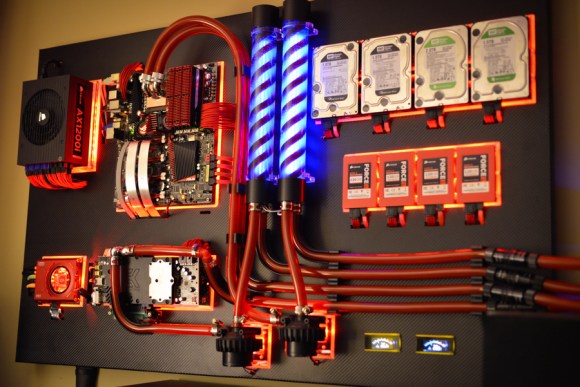
LED Retrofit For Vintage Edge-lit Numeric Display Modules

edge-lit-led-retrofit

This single digit display is an old edge-lit module that [Ty_Eeberfest] has been working with. The modules were built for General Radio Company and have a really huge PCB to control just one digit. [Ty’s] modules didn’t come with that driver board, so he was left with the task of controlling an incandescent bulb for each digit. After a bit of thought he figured it would be much easier to just replace the edge-light bulbs with a set of LEDs.

We’ve seen these exact modules before, referenced in a project that created an edge-lit Nixie tube from scratch. Each digit in the display is made from a piece of acrylic with tiny drill holes which trace out the numerals. The acrylic is bent so that the edge exits out the back of the module where it picks up light from the bulb. [Ty] laid out his circuit board so that each LED was in the same position as the bulb it was replacing. As you can see, his retrofit works like a charm.

Continue reading “LED Retrofit For Vintage Edge-lit Numeric Display Modules”

Drinking Games And Digital Logic

Untitled-1

For those of you who might have forgotten, let’s go over the rules of Centurion. The object of the game is for every minute, for 100 minutes, drink a shot of beer. It doesn’t sound like a lot, but after completing the challenge you’ll have had 3 liters of beer (or about eight and a half 12 oz cans) in just under two hours. When [Peter] played Centurion, he found the biggest problem was – understandably – keeping track of the time and who drank what. For an upcoming weekend of drinking, [Peter] decided to solve this problem once and for all with shift registers and seven-segment displays.

[Peter]’s Centurion score box comes in two parts. The first and largest part of the build is the main board housing an ATMega8 microcontroller and a huge two digit seven-segment display to keep track of the countdown until the next shot. Two other boards house eight additional two digit seven-segment displays for each player, incremented every time a player presses a giant arcade button.

The entire build is designed around a small travel case that also holds a large battery for cordless drinking parties. Let’s just hope the project is reasonably water-resistant; we can see a lot of spills happening in the future. Check out the video demo below.

Continue reading “Drinking Games And Digital Logic”

Auto Dimmer Hacked Into Keyboard Backlight

keyboard-backlight-auto-adjustment

As the title says, [José Faria] added the ability to adjust his keyboard backlight based on ambient light levels. But that’s just one of the things he did during his hacking extravaganza with this Razer BlackWidow Ultimate.

When he first received the peripheral he didn’t like the blue LEDs used as backlights. So he removed all of them and put in white ones. He doesn’t talk too much about that but we’d image it was a ton of work. The new color was pleasing, but then the ability to adjust their brightness started to irritate him. There are four predefined levels and that’s all you get. Even the GUI which has a slider for adjustment couldn’t go outside of those levels.

His solution was to augment the controller with his own. He patched in an AVR chip to the transistor which controls the low side of the LED circuits. While at it he also noticed that the keyboard case was actually translucent. This let him hide a photosensor inside which automatically adjusts the light levels. But he did it in a way that still allows him to use the original functionality with the flip of a switch. See for yourself after the break.

Continue reading “Auto Dimmer Hacked Into Keyboard Backlight”

Old LED Marquee Turned Embedded Video Player

driving-led-marquee-with-rpi

[Sprite_TM] is was sent an old LED Marquee by an anonymous fan of his hacking projects. The display isn’t full color, but it’s large — 224 by 48 pixels — and he figured he could render some okay images with the bi-color diodes. In the end, he replaced the controller and turned it into a video player.

The original system work well enough, but the 100 MHz 486 industrial style PC that drove the display seems a little comical these days. After giving it a spin and testing out how it drives the display [Sprite] hooked up an FTDI chip and managed to get it playing video from his computer. Above you can see part of the opening sequence of The Simpsons.

Now that he had learned its secrets he set out to give it an embedded controller. His first attempt was with a Carambola board which he’s worked with before. That proved to be a little slow for all the pixel data he was pushing so he upgraded to a Raspberry Pi and never looked back. You can see the demo video after the jump.

Continue reading “Old LED Marquee Turned Embedded Video Player”

Mood Lamp/notifier Uses Neat Modular PCB Design

mood-lamp-with-modular-electronics

Not only does this mood lamp which [J. Sutton] built look great, but we love the modular design he adopted when building the circuit boards.

If you’re building something that is going to sit on your desk for some time it just has to look good. We think that he achieved that, using a small block of oak as the base, and a cloudy white cube of unknown origin as a diffuser. Notice that the different colors are not mixed. There’s a baffle inside the diffuser that keeps them separate as early testing showed any combination of intensities was resulting in nearly the same shade of color.

The part we really like is the modular design of his circuit boards. The project is based around a Teensy++ 2.0 board. He first built a PCB baseboard which feature two SIL sockets to accept the legs of the Teensy. There is a third SIL socket which accepts some long legs from the LED host board, letting it perch on top of the Teensy.

Continue reading “Mood Lamp/notifier Uses Neat Modular PCB Design”

Asynchronous Fireflies Use Few Parts

led-firefly

[Karl Lunt] wrote in to share his LED firefly project. His goals for the project were to develop a low-power, low parts count module that can sense when it’s dark and then mimic the blinking patterns you’d associate with its biological namesake.

We like his design which uses a coin cell battery holder as the chassis for the project. The ATtiny13 driving the hardware is held in place by the two power wires. This lets him flash new firmware by rotating the chip and plugging in a little adapter he build. The LED connection might look a bit peculiar to you. It has a resistor in parallel, which doesn’t satisfy the normal role of a current limiting resistor. That’s by design. [Karl] is driving the LED without any current limiting, which should be just fine with the 3V battery and short illumination time of the diode. The resistor comes into play when he uses the LED as a light sensor. Past firefly projects included light dependent resistors to detect light and synchronize multiple units. [Karl] is foregoing the LDR, using the LED with a resistor in parallel to combat the capacitive qualities of the diode. As we mentioned, this senses ambient light, but we’d love to see an update that also uses the LED to synchronize a set of the devices.

Another Way To Look At Charlieplexing

Charlieplexing is a technique that allows you to drive a larger number of LEDs than wouldn’t be possible with the same number of I/O pins on a traditional multiplexed matrix. If we lost you there just think of it as lots of blinky lights connected to a small number of pins. It works by leveraging the one-way nature of a diode. Current will only flow through an LED in one direction so if you hook up your display in a clever way you can drive multiple LEDs from one I/O by switching the polarity of that pin between voltage and ground. [M.Rule] recently looked at using Charlieplexing with LED modules. His conceptual approach to the problem is different from those we remember seeing before and it’s worth a look.

Instead of just using the formula to calculate how many LEDs he can drive [M.Rule] is using a table of I/O pins to establish how many and in what order these displays can be connected. Each colored set of blocks represents an LED module. The graphic above shows how 18-pin can be utilized. He even filled in the unused pin combinations with input buttons.