Visitors at the Garden D’Lights in Bellevue, Washington had a problem. While touring the holiday lights show, they kept straying off the path. The event organizers tried some simple LED arrows, but they were just more points of light among a sea filled with them. This is when [Eric Gunnerson] was asked to help out. He’s apparently had some experience with LED animations, even cooking up a simple descriptor language for writing animations driven by an ESP32. To make the intended path obvious, he turned to a PVC board with 50 embedded WS2812 pixels –RGB controllable LEDs. The control box was a USB power adapter and an ESP8266, very carefully waterproofed and connected to the string of pixels. The backer board is painted black, to complete the hardware. Stick around after the inevitable break, to get a look at the final
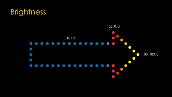
The description of the build process is detailed and contains some great tips, but without a clever LED animation, it’s still of questionable utility. The pattern chosen is great, with the LEDs being blue most of the time, and a flame-like gradient chasing through the arrow every couple seconds. It’s obviously different from the lights of the show, and seems to be a real winner. [Eric] has published his code, with the sheepish caveat that he had to reinvent the wheel once again, and couldn’t reuse any of his previous LED animation work on this one. It’s a simple hack, but a great build log, and an effective solution to a subtle problem. And if addressable LEDs are your thing, check out our other hacks!