New Part Day: Two Millimeter Addressable LEDs

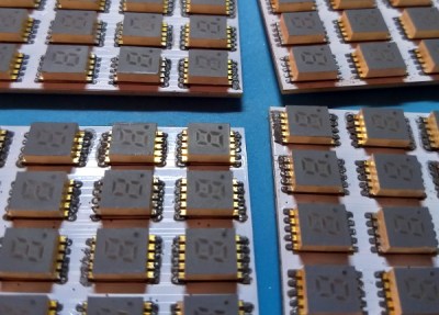
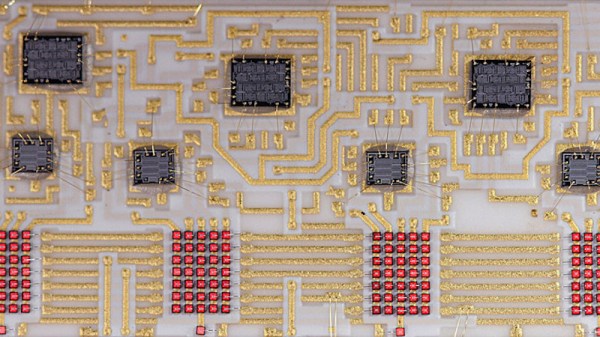
The WS2812, or “Neopixels”, or whatever you want to call them, are the standard when it comes to adding blinky to anything. These chips are individually addressable RGB LEDs, which you’ve seen in many LED strips and a thousand other products. These LEDs are rather big compared to normal, dumb LEDs, measuring 5 mm on each side. Here are WS2812s packed into a 2 mm x 2 mm square package. It’s the smallest and brightest blinky that works the same as the WS2812s you know and love.

This is the latest product from Worldsemi. We’ve heard of these before, but damned if we could find a supplier or even a price. Now they’re on AliExpress, at a price of $8 USD per 100, shipping not included.

Electrically, these appear to have the same properties of the normal, 5050-size WS2812 LEDs. Apply power and ground to two pins, send data in on one pin, and connect the next LED in the strand to the remaining pin. Yes, it requires a bit of work to turn this into a display, but microcontrollers are very fast now and have plenty of RAM. Attach a BeagleBone and you’ll be able to drive as many as your glowing heart desires.

If you’re wondering what the coolest project imaginable for these LEDs is, here’s the math: the largest (common) PCB panel for your random board house is 16 by 22 inches. Assuming a 3 mm pixel pitch, that means the largest PCB display you can make with these LEDs is 135 by 186 pixels, call it 120 by 180 just to make things easy. That’s 21,600 LEDs, at a cost of about $2,000. I would not recommend reflowing these, and assuming soldering a LED every thirty seconds, it will take about a month to solder them all by hand. There’s your project, now get to it.

Epoxy LED Cube Looks Sleek, And Flashes To The Beat

If there’s one thing that’s universally popular in these polarizing times, it’s colorful glowing objects. LEDs reign supreme in this area, and we’re accustomed to seeing all manner of fun flashy devices hit the tips line. Today is no different, and we’ve been looking at [Modustrial Maker]’s stylish epoxy LED cube.

The build starts with the casting of a black epoxy cube, with a cutout near the top in which the LEDs will be installed. A melamine form is used, with aluminium foil tape, caulk and paste wax to help seal it up. After releasing the cast from the form, there were some unsightly voids which were swiftly dispatched, by trimming the block down with a table saw. With the block cut to size, LED strips were installed, and the light cavity sealed with hot glue before white epoxy was poured in as a diffuser. All that’s left was a simple matter of polishing the cube and installing electronics.

The cube runs from a single-cell LiPo battery, and there’s a wireless power receiver and charging module to keep the power flowing. The cube can be used on most wireless phone chargers, as well as its own dedicated charging base. The LEDs are controlled by an off-the-shelf module, which offers a variety of flashing displays as well as a music-reactive mode.

While the electronics side is done with off-the-shelf parts, the real art in this piece is in the build of the cube. Its glossy, attractive form would look stunning on any coffee table or bedside shelf.

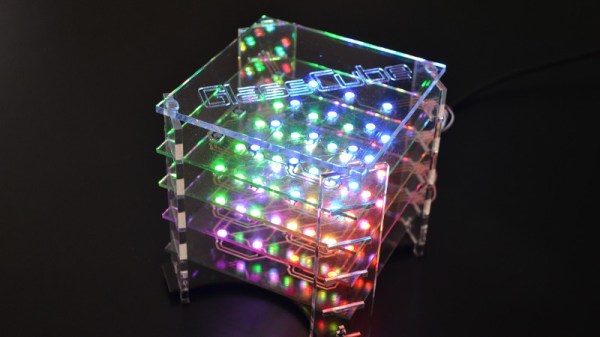
LED cubes are a great rabbit hole to go down on your lunch break. This OpenGL-enabled build is particularly impressive. Video after the break.

Continue reading “Epoxy LED Cube Looks Sleek, And Flashes To The Beat”

The Battery Is Part Of The Art

A work of art is appreciated for its own sake and we will never tire of seeing stunning circuits from microscopic dead-bugs to ornate brass sculptures. We also adore projects that share the tricks to use in our own work. Such is the case with [Jiří Praus] who made some jewelry and shared his templates so we try this out ourselves.

The materials include brass wire, solder, and surface-mount LEDs. Template design expects a 1206 light, so if you step outside that footprint, plan accordingly. The printable templates are intuitive and leverage basic wire jewelry making skills. Some good news is that flashing LEDs are available in that size so you can have an array of blinkenlights that appears random due to drifting circuits. Please be wary with RGB lights or mixing colors because red LEDs generally run at a lower voltage and they will siphon a significant chunk of a coin-cell’s power from a competing green or blue. How else can these be personalized?

[Jiří]’s charms are just the latest of circuits that capture our eyes and tickle our ears.

LED Music Visualizer Bespeckles Your Bedroom

When it comes to wall-mounted ornamentation, get ready to throw out your throw-rugs and swap them for something that will pop so vividly, you’ll want to get your eyes checked. To get our eyes warmed up and popping, [James Best] has concocted a gargantuan 900-RGB-LED music visualizer to ensure that our bedrooms are bright and blinky on demand.

Like any other graduate from that small liberal-arts school in southern California, [James] started prototyping with some good old-fashioned blue tape. Once he had had his grid-spacing established, he set to work on 2-meter-by-0.5-meter wall mounted display from some plywood and lumber. Following some minor adhesive mishaps, James had his grid tacked down with Gaffers tape, and ready for visuals.

Under the hood, a Teensy is leveraging its DMA capabilities to conduct out a bitstream to 900 LEDs. By using the DMA feature and opting for a Teensy over the go-to Arduino, [James] is  using the spare CPU cycles to cook out some Fourier-Transformed music samples and display their frequency content.

We’ve covered folks proving the concept of driving oodles of WS2812B LEDs over DMA; it’s great seeing these ideas mature into a fully-featured project that lands on the walll. For more on chatting with WS2812B LEDs over DMA, have a look back into our archive.

Continue reading “LED Music Visualizer Bespeckles Your Bedroom”

Visualizing LEDs For More Efficient Pin Packing

The archetypal “blink an LED” is a great starter project on any platform, but once the bug takes hold that quickly turns into an exploration of exactly how many LEDs a given microcontroller can drive. And that often leads to Charlieplexing. A quick search yields many copies of The Table describing how many LEDs can be driven by a given number of pins but that’s just the most rudimentary way to describe it. Way back in 2013 [M Rule] developed a clever trick to describe the number of LED matrices which can be driven by a Charlieplexed array of a given size that makes this process much more intuitive. The post may be old, but we promise the method is still fresh.

[M Rule] was specifically looking to drive those big, cheap single color LED matrices which are often used to make scrolling signs and the like. These parts are typically a matrix of LEDs with a row of common cathodes and one of common anodes. Internally they are completely dumb and can be driven by row/column scanning, or any other way a typical matrix can be controlled. The question is, given known matrix sizes, how many can be driven with a a number of Charlieplexed LED drive pins?

The first step is to visualize the 1D array of available pins as a 2D matrix, as seen to the right. Note each numbered pin is the same on the X and Y, thus the black exclusion zone of illegal drive pin combinations slicing across the graph (you can’t drive an LED connected to one pin twice). The trick, if one were to say it resides in a single place, would be titling the axis anode and cathode, representing two “orientations” the drive pins can be put in. With this diagram [M Rule] observed you can simply drop a matrix into the array. If it fits outside the exclusion zone, it can be driven by those pins!

To the left is what this looks like with two 8×8 matrices, one connected between pins 1-8 and 9-16, the other connected between 9-16 and 1-8. This isn’t terribly interesting, but the technique works just as well with single LEDs and any size matrix, including 7-segment displays. Plus as long as an element doesn’t overlap itself it can wrap around the edges leading to some wild visuals, like 14 RGB LEDs on seven pins to the right.

The most extreme examples are pretty exotic. Check out [M Rule]’s post for the crown jewel; 18 pins to drive six 5×7 modules, six 7-segment displays, 12 single LEDs, and 18 buttons!

If this color coded diagram seems familiar, you may be remembering [openmusiclabs]’ excellent diagram describing ways to scan many of buttons. Or our coverage of another trick of matrix topology by [M Rule] from a few weeks ago.

IKEA Cloud Lamp Displays The Weather With An ESP8266

The IKEA DRÖMSYN is a wall mounted cloud night light that’s perfect for a kid’s room. For $10 USD, it’s just begging for somebody to cram some electronics in there and make it do something cool. Luckily for us, [Jodgson] decided to take on the challenge and turned this once simple lamp into a clever weather display. It even still works as an LED lamp, if you’re into that sort of thing.

After stripping out the original hardware, [Jodgson] installed a Wemos D1 Mini and a string of fourteen SK6812 RGB LEDs that run down the length of the cloud’s internal structure. Weather data is pulled down with the OpenWeatherMap API, and conditions are displayed through various lighting colors and effects.

Sunny days are represented with a nice yellow glow, and a cloudy forecast looks like…well it’s already a white cloud so that one’s pretty easy. If rain is expected the cloud turns blue and the bottom LEDs flicker a bit to represent raindrops. When there’s a thunderstorm, the cloud will intermittently flash random LEDs on the strip a bit brighter than their peers; a really slick effect that gets the point across immediately.

This isn’t the first time we’ve seen somebody take a cheap light from IKEA and turn it into something much more impressive with the ESP8266. Just like with that previous project, we wouldn’t be surprised to see this particular modification popping up more in the future.

New PCB Revives Ancient Bubble LED Displays

For those of us who remember LED calculators, the HP 5082-7400 series red “bubble” displays hold a special charm. Available in 3, 4, or 5-digit varieties, these multiplexed 7-segment displays provided countless hours of entertainment to those who would spell upside-down words on their pocket calculators. In case you happen to be lucky enough to have access to a few of these beautiful vintage display sticks, [Gigawipf] has designed a small driver PCB that lets you easily interface them to a modern microcontroller.

At the heart of the board, aimed at either the 5082-7405 or 5082-7415 5-digit modules, are a pair of 74HC595 shift registers in tiny QFN packages. Five lines from one register drive one of the common cathodes for the selected digit, while the other register drives the eight anode lines through 330-Ohm resistors. The boards are slightly smaller than the width of the displays allowing you to stack them seamlessly for more digits, and eight header pins on each allow you to plug them into solderless breadboards for prototyping. The result is easy to drive with some simple code, and [Gigawipf] provides an example for Arduino as part of the project. The Eagle design files are supplied, as well as Gerbers for those who just want to have some boards made. This sounds like a great way to get some of these vintage displays going again.

If you can’t find any of these displays to play, with, you can try making some larger digits from individual surface-mount LEDs.