Mbed And A Few Resistors Runs Console, VGA, And PS/2

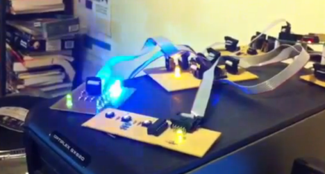
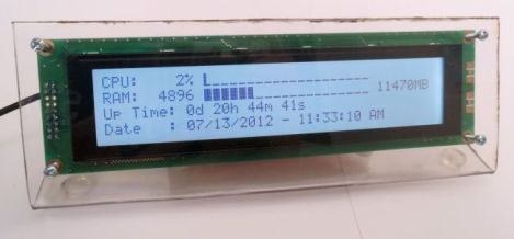
[Jordan] writes in to show us a project he has been working on called MbedConsole. Living up its name [Jordan] has managed to run a 640×480 VGA output, PS/2 port and console all from the mbed itself. We really mean from an mbed only; no extra hardware is required aside from a few resistors and connectors, a VGA monitor and PS/2 keyboard. The code is open source and links are included in the blog. There are even instructions for including your own graphics.

There are a few things to tackle still, like SD card support. Currently the PS/2 keyboard lights for caps-lock are not functional. [Jordan] would love to know what else we’d see going on something like this, with 400k of flash and 20k RAM left there certainly is a bit of room for some interesting stuff. One of his main goals is to get rid of the C interface and port an interactive shell over that could do something like BASIC or Forth (to give it that retro environment feel). We have seen the mbed in a handful of projects, what do you think?

Programming A Microcontroller One Bit At A Time

Imagine you’re stuck on a desert island, hundreds of miles away from the nearest person, and you finally have time to finish that project you’re working on. You have a single microcontroller, but you’re lacking a computer and you need to program an ATtiny13. How do you do it? [androidruberoid] figured out how to manually flash a microcontroller (Russian, surprisingly good translation) using just three switches and a lot of patience.

[androidruberoid]’s ATtiny13 – like nearly all Atmel microcontrollers – are programmed using an SPI interface. This interface requires four signals: SCK, a data clock, MOSI, the data line from master to slave, MISO, data from slave to master, and RESET. By connecting these data lines to buttons, [androidruberoid] is able to manually key in new firmware one byte at a time.

This technique of manually programming bits relies on the fact that there is no minimum speed for an SPI interface. In the video after the break, you can see [androidruberoid] manually programming an ATtiny13 with a simple program. It only lights up an LED, but with enough patience he could key in a simple ‘blink a LED’ program.

Continue reading “Programming A Microcontroller One Bit At A Time”

USBPIC Controls Just About Anything

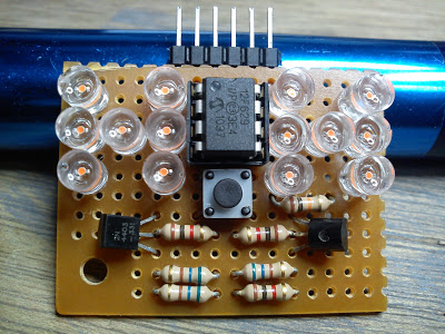
Over the last few years, [Michael] has been developing a PIC microcontroller board. He calls his project USBPIC, and with the addition of a few FET drivers, H-bridges, and LED drivers his homemade dev board can handle just about anything thrown at it.

[Michael]’s board is build around a PIC18F2455 microcontroller with both an In Circuit Serial Programming header and support for a USB port included. Instead of going for a modular format where the board can expanded through shields or expansion cards, [Michael] decided to make three different versions of the USBPIC.

The TRANS USBPIC includes eight FETs for switching off high current devices totaling 32 Amps. The MATRIX board has twice as many outputs as the TRANS board, but uses ULN2803 or UDN2982 chips for driving smallish-current devices. Finally, the HBSW board takes a TRANS board and replaces four FETs with a an L298 H-bridge chip for driving two DC motors.

For what [Michael] lost in modularity, we think he gained a very tidy microcontroller board capable of driving everything from robots to LED matrix displays.

Reading Bare NAND Flash Chips With A Microcontroller

NAND flash, the same memory chips found in everything from USB thumb drives to very expensive solid state disk drives, are increasingly common. As they (partially) serve as the storage for cellphones, Wiis, routers and just about every piece of consumer electronic devices, you’re probably surrounded by dozens of NAND chips at any one time.

[Sprite_tm], hacker extraordinaire, put up a build a few years ago where he was able to read the contents of NAND Flash chips using a PC parallel port. It’s getting rather hard to find a parallel port on a PC anymore, so he updated his build to read Flash chips off of a USB port.

There are two main components of [Sprite_tm]’s build. First, to read the Flash chip, he needed a way to break out the pins on the very tiny TSOP48 package. [Sprite] found a neat little socket for these chips on eBay for about 10 Euros.

Communicating with the Flash chip via USB was a little harder. [Sprite] knew he needed USB 2.0, but not many microcontrollers have that implemented. Luckily, the FTDI FT2232H has USB 2.0, along with the very nice feature of being able to read data and address pins directly from the Flash chip. After a bit of soldering, [Sprite_tm] was left with the device seen above.

[Sprite_tm] found a nice library to bitbang the pins on the FTDI chip and request one page of memory from the Flash chip at a time. The device works as advertised, but it’s still a bit slow at 250 kBps. [Sprite] figures he can increase the speed of reading a Flash chip by requesting multiple pages at a time, but it’s still orders of magnitude faster than the old parallel port solution.

There’s a good bit of software [Sprite] posted to help him (and possibly others) read bare NAND flash chips via USB. This means if you have a broken USB Flash drive or SD card, it’s possible to desolder the chip and read it with your own controller. Interpreting the blocks of data recovered from a Flash drive as a file system is another story, but it’s still a fairly remarkable build.

Programming Without A Toolchain; Crafting PIC Op Code By Hand

We’ve been living a life of luxury, writing our microcontroller code in a text editor and using — of all things — a compiler to turn it into something the chip can use. [Dan Amlund Thomsen] shows us a different way of doing things. He’s actually crafting the operation codes for a PIC microcontroller by hand. We’re glad he’s explained this in-depth because right now we feel way over our heads.

His program is pretty simple, it blinks a single LED and he’s chosen t work with a PIC 12F1840. The first order of business is to issues the words that configure the chip using 14-bit binary values from the datasheet. From there he goes on to write the program in assembly code. At this point he could pretty much just run this through the assembler, but he’s really just getting started now. He walks through the format necessary to package the configuration words, then goes on to illustrate the translation of assembly commands to binary op codes. We’re not sure we’ll ever get around to trying this ourselves, but it was certainly fun to read about it.

Help Create A Universal ARM Programmer

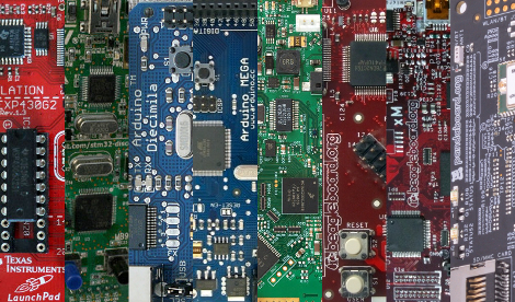
The new crop of ARM Cortex M0/M3/M4 microcontrollers have a lot of interesting features for developers. In addition to supporting drag and drop programming via USB, the same hardware can also be used as a debugger. Setting breakpoints and inspecting memory at any point in the code is a wonderful feature, but not all the new ARM dev boards we’ve seen support this feature.

The folks over on SimpleCortex have a solution to this problem, but they need your help. To get their CMSIS-DAP hardware working with Open Source tools, they’re looking for a few good programmers and hardware developers to build a toolchain.

Right now, the hardware only works with Keil development tools. A closed source development environment is no good to anyone, so if you have some experience writing drivers and such, send the guys at SimpleCortex an email. They’ll give you a free board in return for a contribution to building an open source ARM toolchain.

Common sense requires us to mention that you should probably only send these guys an email if you actually plan on working on this problem. Still, it’s a great opportunity to contribute to open hardware.

Video Preview: New IOIO Prototype

We got our hands on this prototype of the new IOIO design. It’s a breakout board that makes adding hardware to an Android device pretty easy.  [Ytai Ben-Tsvi] sent it our way, and took a bit of time to explain some of the differences between this board and the original version. You can see our video preview embedded after the break.

The size and form factor of the board remain the same, but the choice and layout of parts has changed. Most obviously, the USB-A connector is gone, replaced by a USB mini-B micro-B connector. This makes it possible to use the board as a USB-on-the-go device, or as a USB host device with the help of an adapter that will ship with the board. The JST connector is for external power. The previous revision included a footprint for it but it was never populated. There has also been an upgrade to the voltage regulation circuit, using a newer part as the switch-mode regulator.

There was a last-minute bug discovered in the layout. [Ytai] wants iron-clad 5V to ground short protection and is re-spinning the board to ensure he achieves that goal. He can’t say for sure, but as we mentioned in our previous post about the prototype, a price cut is planned. It could cut the current price of $50 down to just $30, but that won’t be decided until all of the choices have been made for the first production run.

Continue reading “Video Preview: New IOIO Prototype”