AVR Programmer Made Without A Programmer

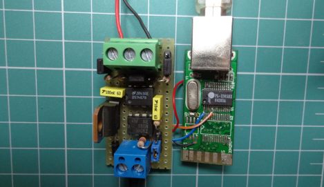
[blueHash] uses this cheap development board as an AVR programmer. What’s interesting to us is that it solves the chicken-or-egg problem that is usually encountered when bootstrapping a programmer. We’ve written about this issue before. Most programmers use microcontrollers, which first need to be flashed using a programmer. But it turns out the chip on this dev board has a DFU mode which gets around that conundrum.

He grabbed a uSD dev board for about $6. It’s got a crystal, an ATmega32u4 chip, and on the other side there’s a MicroSD card slot. We looked around and found an Atmel Datasheet (PDF) which describes the Device Firmware Upgrade mechanism. The AVR devices which support DFU are factory configured to use it. This dev board is designed to use DFU so all [blueHash] needed to do is find and configure a ISP firmware package that worked with this chip.

Dumping A C64 Kernel

[Blark] picked up a couple of Commodore 64 machines on Craig’s List so that he could play around with the SID chips inside. But there’s some other fun stuff in there and his attention was drawn to the PROM which stores the kernel. He thought it would be a fun adventure to build a ROM dumper capable of storing binary images.

In the video after the break you can see that when powered up the dumper immediately starts streaming hex values to the terminal. The system is set up to feed a Python script which packs the data stream into an image file. The reading is done by a PIC 18F4520, streaming the data in at 9600 baud with a generous delay between each address read to get the cleanest read possible. He had a bit of help from the AVR Freaks to get to this point.

We’d guess he’s going to pull the image off the chip several times and compare results to filter out any possible data corruption. From there we’re not sure what he’ll do with the files but there’s always the possibility of making is own emulator using this kernel image.

Continue reading “Dumping A C64 Kernel”

Art Controller: Relay Board With Switches For Timing

Meet the Art Controller, a new dev board available over at Evil Mad Scientist Laboratories. It provides a drop-in solution for switching higher voltage loads (but not mains). The thing we like most about it is the ability to alter a switching delay without reprogramming the firmware.

The board uses an ATtiny2313 for control. It’s fed regulated 5V power from the on-board 7805 linear regulator. The relay can handle a 24V DC or 40V AC load, which is targeted at an audience that needs electronic switching for art-related devices but doesn’t want the hassle of designing a circuit every time. This offers a single shot, or repeat action, with that bank of DIP switches selecting a delay from once every second, to every 31 hours. It can get its initial trigger from anything that can pull a pin low, like a button, or a coin acceptor.

Keep this in mind. The open source nature of the project means it could come in handy as a reference design.

STM32 F3 Discovery Dev Board Includes Some Extras

ST Microelectronics keeps kicking out development boards to show off their new ARM processor line. Yesterday they issued a press release announcing the STM32 F3 Discovery Board. As their naming scheme implies, this carries an ARM Cortex-M3 processor, but compared to the F0 Discovery board (which we loved) it’s got several extra goodies built into it.

We took a look at the F3 Discovery product page and it doesn’t look like you can order these quite yet. But click-through to the pricing and you’ll see they’ve set it at $10.90. Digikey lists the board at that price point, Mouser lists it at about $16, but neither supplier has any available. We also didn’t see a link for free boards like when the F0 model was released. If you do come across a giveaway link please tip us off about it.

Okay, now let’s discuss those extras. We think this dev kit could be used as an IMU for applications like a quadcopter or a self-balancing robot. That’s because it has a gyroscope and an accelerometer. It’s also got ten LEDs, eight of which are arranged on that white circle. We’d guess that layout is for displaying orientation data from the IMU sensors. There’s also a second USB port to use when developing USB applications for the chip.

Like the other boards in the Discovery family this has the STlinkV2 built-in to use as a programmer. We don’t know if OpenOCD has support for the F3 chipset yet, which is what we’ve been using to program STM chips in a Linux environment.

2708 EPROM Dumper

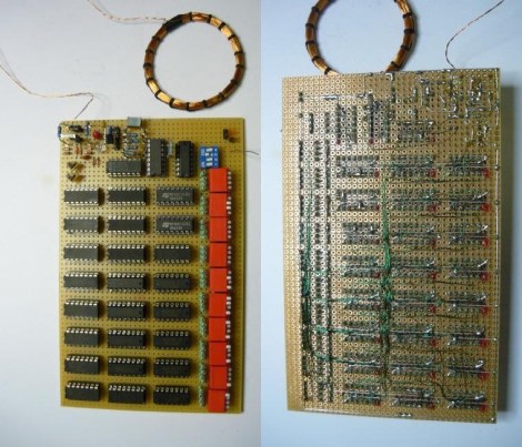
[Andrea “Mancausoft” Milazzo] has been restoring old equipment which often contain EPROM chips. He thought he was all set with an EPROM reader which easily dumped the data from 2716 chips and a few others. But he found that the hardware was unable to read 2708 and 2704 chips. His solution was to build a PIC-based EPROM dumper.

You may remember from some of our recent features that these chips are something of a ticking clock. They store program code and other information vital to the functioning of old hardware. Since they’re erased with UV light, years of exposure to ambient light can zap some of the data.

The specs needed to read a chip of this type are rather rudimentary. There are ten address pins and eight data pins. [Andrea] also needed a way to get data from the microcontroller to a computer for backup. He uses two more pins for this purpose, bringing the I/O count to 20. He went with  PIC 18F4610 and built the rest of the reader around it.

Rickrolling Remote Control Prank

This device is a prank or gag that [Eric Heisler] came up with. It will intercept IR remote control codes and play them back after a bit of a delay. The example he shows in the video (embedded after the break) catches the television power signal from a remote, then sends it again after about thirty seconds. This shuts off the TV and would be extremely annoying if you were unable to find the device. Fortunately (for the victim), [Eric] included a piezo buzzer that Rickrolls after sending each code. Just follow that tune to find the offending hardware.

He chose to use an ATtiny10 microcontroller. It looks like it’s realizing its full potential as the six-pin package use all available I/O to control the IR receiver module, an IR led, and the buzzer. It runs from a coin cell without regulation and the circuit was free-formed on a tiny surface mount breakout board which hosts the microprocessor.

Frequency Analyzer Built From The New Stellaris Launchpad

Here’s the first project we’ve seen for the new Stellaris Launchpad. It’s a frequency analyzer which displays a graph on an 8×8 LED module. What’s that you say? You haven’t received your new Launchpad board yet? Neither have we since they don’t start shipping until the end of the month. But [EuphonistiHack] works as a software dev for TI and snagged one of the early development units.

Hardware is rather simple. He uses an OpAmp to feed audio from his laptop to the ARM processor. The 8×8 LED module is an MSP430 booster pack that is addressed via SPI. On the software side of things he’s really taking advantage of hardware peripherals to simplify his work. A timer triggers each ADC reading which in turn writes the values using uDMA. Digital Signal Processing (available as a CMSIS library for many ARM chips) is then used to translate the ADC value to one that can be displayed on the LEDs. Check out the video after the break to see the final version.

The Hackaday writers are looking for an easier name for this hardware than “Stellaris Launchpad”. It doesn’t seem to lend itself to a shorter name, like RPi or Raspi does for the Raspberry Pi. If you’ve got a catchy nick name for the new board please share it in the comments.