VGA Video Output With An ATtiny

vga_video_attiny

[Fernando] is working on creating a game at home, with live scoring displayed on a large LCD TV. He’s keeping mum as to what the game entails, but he was more than happy to spill the details on how he planned to use the television as a wireless scoreboard.

The writeup is the first part in what will likely be a substantial series of progress reports, covering how he used an ATtiny45 to drive his LCD display. Eventually, the scoreboard will use a Bluetooth adapter for wireless input, but his immediate goal was to get the display running properly.

He explains how he uses the tiny micro and its limited set of I/O pins to drive the display, dipping into some of the technical details along the way. He discusses how he worked out the timings of the VSYNC and HSYNC pulsing, as well as how how the characters are actually drawn on the screen.

The article isn’t overly heavy on the technical details, and he has sample code available so you can take a look at how the VGA magic was done, so be sure to check it out.
Vowel Recognition Using An ATmega644

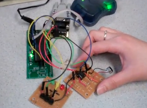
[Youchun Zhang] and [Annie (Wei) Dai] found a way to differentiate vowel sounds using an ATmega644 as their final project for a microcontroller design class. Voice recognition is not out of the ordinary, but most of the time it uses a computer, smart phone, or specially designed hardware. This implementation uses an ATmega644, a microphone connected via an op-amp, and a few buttons. In the demonstration after the break you’ll see that they’re outputting status data to Putty via an RS232 connection, but that’s just so you can see what’s going on inside the chip. It’s what’s doing all of the hard work.

In order to tell the difference between vowels, the waveforms of each sound were analyzed using MATLAB during the research phase. That analysis allowed the team to assemble data for each sound that contained the peaks least often found in the other sounds. Now the microcontroller analyzes incoming sound, comparing it to that data set. The analysis is snappy, happening in real-time thanks to the team’s use of the Fast Walsh Transform. It turns the sound into a set of square waves and presents them as a 64 bit sample. The result can be used as a password protection scheme, but as far as we can tell this doesn’t key to just one person, anyone who knows the vowels of the password can use it.

Continue reading “Vowel Recognition Using An ATmega644” →

Making Oscilloscopes From ARM Development Boards

If you’ve got an ARM development board gathering dust in the corner of your shop, perhaps you could repurpose it as an oscilloscope. [Arend-Paul Spijkerman] was able to use an mbed and LPCXpresso as the hardware end of an oscilloscope. He didn’t use a standalone screen as a display, instead opting to push the scope readings from the hardware to a computer for display. This was greatly simplified by using StampDock as a basis for the GUI.

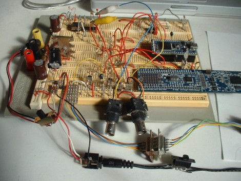
His circuit diagrams calls for an RS-232 connection for the LPCXpresso but not for the mbed. We’re not quite familiar enough with the mbed to know why, but perhaps those in the know can clue us in by leaving a comment. The probe connections are quite simple, each made up of a voltage divider and a pair of diodes. But the breadboard above looks much busier because it has two oscilloscope circuits built on it, and there’s a 10 MHz clock and a 4040 ripple counter which were used to provide a test signal.

Using An MSP430 For Time Lapse Photography

vistaquest_keychain_timelapse_msp430

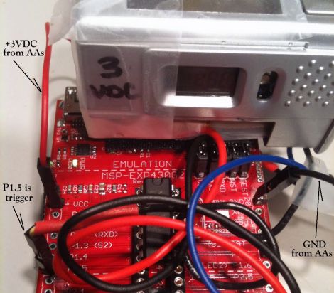
Hackaday reader [onefivefour] had an old VistaQuest VQ1005 keychain camera kicking around, and wanted to do something useful with it. A while back he hooked up a 555 timer and did a bit of time lapse photography, but he wanted more control over the process. Specifically, he desired the ability to tweak the delay between shots in a more granular fashion, as well as way to prevent the VistaQuest from going to sleep after sitting idle for 60 seconds.

His weapon of choice to get this task done was an MSP430, since the microcontroller can be found quite cheaply, and because it is relatively easy to use. He added a few header pins to the LaunchPad board wiring them up to the camera’s trigger as well as the on/off switch. When the wire connected to the trigger is pulled low, the camera snaps a picture. The wire connected to the on/off switch is always held low, ensuring that the camera is on and ready to go whenever it’s time to take a shot.

It’s a relatively simple project, but definitely useful. While there are many ways to build an intervalometer, the MSP430 is a great platform to use, especially for beginners.

Stick around to see a quick video [onefivefour] put together, showing off his time lapse rig’s capabilities.

Continue reading “Using An MSP430 For Time Lapse Photography” →

Bootloader Burning Basics

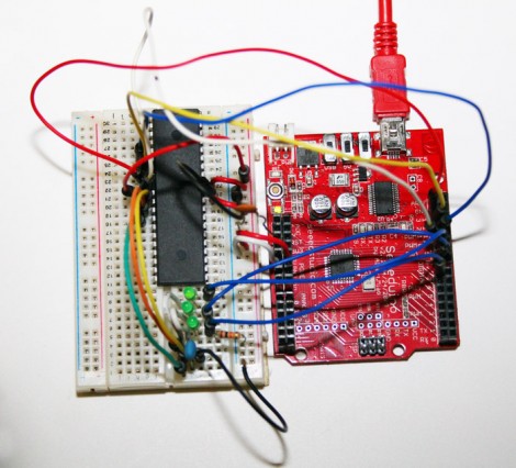
[Charles Gantt] and a few others were having trouble burning the Sanguino bootloader to an ATmega644 chip. With some help from the [Nils Vogil] via the RepRap IRC [Charles] got it worked out and wrote a guide for burning the bootloader using an Arduino as an ISP programmer.

We’re not familiar with the specifics of the Sanguino bootloader, but [Charles] mentioned that he was unable to flash it onto the AVR chip without a resonator. The resonator serves as an external clock source for the chip. We’d bet the programming process changes the fuse settings on the chip to use an external source. Without that source, you won’t be able to communicate with the chip afterwards.

The solution just adds the resonator to the programming circuit. This should be useful when burning any bootloader using an Arduino. But it does make us wonder if there isn’t an alternative method that would let you draw the clock signal from the Arduino itself?

A Stackable Motor Driver Shield For The Arduino

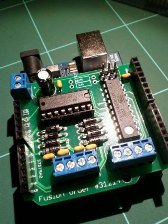
The Arduino has been used for many purposes, and  “shields” are available to make many common tasks easier.  However, [Nick] wanted a stackable motor driver shield, so he build one himself!. There are many motor driver shields available for the Arduino, however, there aren’t any that allow one to drive as many motors as were needed for his project, and none that were stackable.

[Nick] had no experience designing and fabricating a custom board, but decided to try his hand at it anyway. Armed with a free version of [Eagle] PCB design software, he designed the board that he needed then sent it to [Seeed] to be manufactured. According to his article, a quantity of 10 Arduino-sized boards can be purchased for the price of $25. At that price point, some hobbyists may want to consider this option rather than manually creating their own circuit.

According to [Nick], he was able to manufacture his first board with no errors on his first run! Not bad for his first try at something like this.

Shock Yourself To Better Health!

cranial_electrotherapy_stimulation_rig

Flickr user [n Bryan] has been keeping busy lately, trying his hand at developing some cranial electrotherapy stimulation instruments for home use. While visions of [Peter Venkman] electrocuting hapless college students initially came to mind, this sort of therapy is not the same thing, nor as painful as what is depicted in the film.

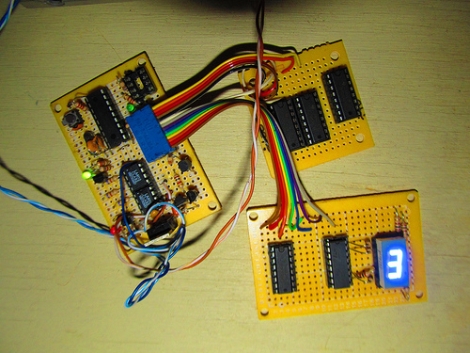
Cranial electrotherapy stimulation relies on small currents which are pulsed along a patient’s skull at specific bioactive frequencies. It is believed that these treatments can have positive responses on the nervous system, and in fact has been approved by the FDA for certain ailments such as insomnia and anxiety. [n Bryan’s] rig is controlled by a PIC 16F88, which generates both the carrier and pre-programmed bioactive frequencies used in electrotherapy sessions.

As with all things that involve strapping electrodes to your head, take caution if you plan on replicating his work in any way, shape or form. With that said, we’d be willing to give it a shot.

[via BuildLounge]