These days, you can get all kinds of cheap power supply modules off a variety of online vendors. A lot of examples from brands like Juntek and Drok often have pretty poor interfaces though, with a couple of tactile buttons and a simple 7-segment display. [rin67630] decided to whip up a better controller with a much more informative display.
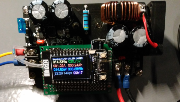
The controller is designed to work with programmable buck converter modules like the DPS3806, Buck3603, and BST900. It’s based on a TTGO ESP32 with an integrated color TFT LCD. It displays voltage at the input and output, the same for current, along with current setpoints. It also allows for control of a fan and charge cycles if so desired, and it has the ability to fetch time from an NTP server for proper scheduling. There’s also a web interface complete with graphs for really diving down into the nitty-gritty. Future plans include adding an MPPT solar charging capability.
If you’ve ever wanted a cheap power supply module with really low-level control and rich data display, this could be just what you need. Meanwhile, you’ve got your own neat power supply in the works, don’t hesitate to drop us a line.