While browsing through his local dollar store, [Taylor] came across a suspicious looking rock that, upon closer inspection, turned out to be a solar garden light. He scooped it up, took it home and cracked it open, modding it to function as a handheld solar flashlight.
Inside was a pathetically small 40mAh rechargeable battery, which he upgraded to a more standard rechargeable AA. The garden rock came pre-built with its own boost converter to kick up the voltage for the LED, but it was fairly dim. We’re guessing [Taylor] didn’t bother reverse engineering the converter and instead simply did some trial and error, but he managed to increase the LED’s brightness by slapping on a different value inductor.
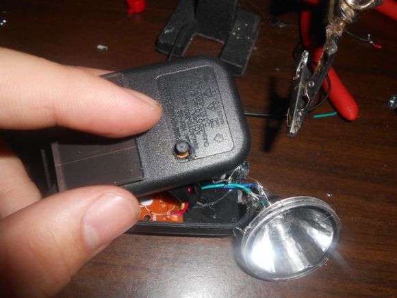
As fun as it may be to have a rock for a flashlight, [Taylor] decided to cobble together a custom case out of a spare USB charger, making a battery holder and adding a pushbutton. The result is a handy solar flashlight that takes around five hours to charge. Check out some other custom lights: a lithium-powered PVC flashlight or one with a snazzier aluminum body and interchangeable heads.