When your steam engine build requires multiple microscopes, including those of the scanning electron variety, you know you’re building something really, really tiny.
All of the usual tiny superlatives and comparisons apply to [Chronova Engineering]’s latest effort — fits on a pencil eraser, don’t sneeze while you’re working on it or you’ll never find it. If we were to put the footprint of this engine into SMD context, we’d say it’s around a 2010 or so. As one would expect, the design is minimalistic, with no room for traditional bearings or valves. The piston and connecting rod are one piece, meaning the cylinder must pivot, which provides a clever way of switching between intake and exhaust. Tiny crankshaft, tiny flywheel. Everything you’d associate with a steam engine is there, but just barely.
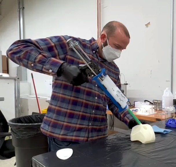
The tooling needed to accomplish this feat is pretty impressive too. [Chronova] are no strangers to precision work, but this is a step beyond. Almost everything was done on a watchmaker’s lathe with a milling attachment and a microscope assist. For the main body of the engine, a pantograph engraving machine was enlisted to scale a 3D printed template down tenfold. Drill bits in the 0.3 mm range didn’t fare too well against annealed tool steel, which is where the scanning electron microscope came into play. It revealed brittle fractures in the carbide tool, which prompted a dive down the rabbit hole of micro-machining and a switch to high-speed steel tooling.
It all worked in the end, enough so that the engine managed 42,000 RPM on a test with compressed air. We eagerly await the equally tiny boiler for a live steam test.
Continue reading “This Tiny Steam Engine Takes A Watchmaker’s Skill To Build”