$40 Ham Antenna Works Six Bands

[My Ham Radio Journey] wanted to see if a “common person” (in his words) could build an effective vertical ham radio antenna. If you look at the video below, the answer is apparently yes.

He started with a 24-foot fishing rod and a roll of 22 gauge wire. The height of the antenna wire is just over 20 feet long and he has several ground radials, as you might expect for a vertical antenna.

Continue reading “$40 Ham Antenna Works Six Bands”

RFID From First Principles And Saving A Cat

[Dale Cook] has cats, and as he readily admits, cats are jerks. We’d use stronger language than that, but either way it became a significant impediment to making progress with an RFID-based sensor to allow his cats access to their litterbox. Luckily, though, he was able to salvage the project enough to give a great talk on RFID from first principles and learn about a potentially tragic mistake.

If you don’t have 20 minutes to spare for the video below, the quick summary is that [Dale]’s cats are each chipped with an RFID tag using the FDX-B protocol. He figured he’d be able to build a scanner to open the door to their playpen litterbox, but alas, the read range on the chip and the aforementioned attitude problems foiled that plan. He kept plugging away, though, to better understand RFID and the electronics that make it work.

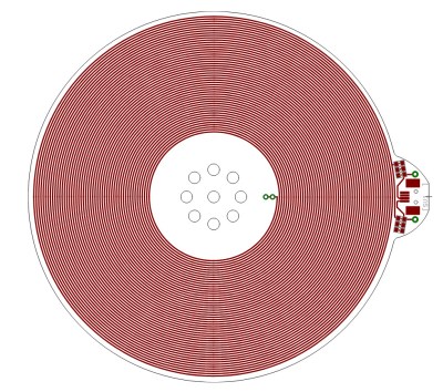
To that end, [Dale] rolled his own RFID reader pretty much from scratch. He used an Arduino to generate the 134.2-kHz clock signal for the FDX-B chips and to parse the returned data. In between, he built a push-pull driver for the antenna coil and an envelope detector to pull the modulated data off the carrier. He also added a low-pass filter and a comparator to clean up the signal into a nice square wave, which was fed into the Arduino to parse the Differential Manchester-encoded data.

Although he was able to read his cats’ chips with this setup, [Dale] admits it was a long road compared to just buying a Flipper Zero or visiting the vet. But it provided him a look under the covers of RFID, which is worth a lot all by itself. But more importantly, he also discovered that one cat had a chip that returned a code different than what was recorded in the national database. That could have resulted in heartache, and avoiding that is certainly worth the effort too.

Continue reading “RFID From First Principles And Saving A Cat”

Junk Box Build Helps Hams With SDR

SDRs have been a game changer for radio hobbyists, but for ham radio applications, they often need a little help. That’s especially true of SDR dongles, which don’t have a lot of selectivity in the HF bands. But they’re so darn cheap and fun to play with, what’s a ham to do?

[VK3YE] has an answer, in the form of this homebrew software-defined radio (SDR) helper. It’s got a few features that make using a dongle like the RTL-SDR on the HF bands a little easier and a bit more pleasant. Construction is dead simple and based on what was in the junk bin and includes a potentiometer for attenuating stronger signals, a high-pass filter to tamp down stronger medium-wave broadcast stations, and a series-tuned LC circuit for each of the HF bands to provide some needed selectivity. Everything is wired together ugly-style in a metal enclosure, with a little jiggering needed to isolate the variable capacitor from ground.

The last two-thirds of the video below shows the helper in use on everything from the 11-meter (CB) band down to the AM bands. This would be a great addition to any ham’s SDR toolkit.

Continue reading “Junk Box Build Helps Hams With SDR”

Schooling ChatGPT On Antenna Theory Misconceptions

We’re not very far into the AI revolution at this point, but we’re far enough to know not to trust AI implicitly. If you accept what ChatGPT or any of the other AI chatbots have to say at face value, you might just embarrass yourself. Or worse, you might make a mistake designing your next antenna.

We’ll explain. [Gregg Messenger (VE6WO)] asked a seemingly simple question about antenna theory: Does an impedance mismatch between the antenna and a coaxial feedline result in common-mode current on the coax shield? It’s an important practical matter, as any ham who has had the painful experience of “RF in the shack” can tell you. They also will likely tell you that common-mode current on the shield is caused by an unbalanced antenna system, not an impedance mismatch. But when [Gregg] asked Google Gemini and ChatGPT that question, the answer came back that impedance mismatch can cause current flow on the shield. So who’s right?

In the first video below, [Gregg] built a simulated ham shack using a 100-MHz signal generator and a length of coaxial feedline. Using a toroidal ferrite core with a couple of turns of magnet wire and a capacitor as a current probe for his oscilloscope, he was unable to find a trace of the signal on the shield even if the feedline was unterminated, which produces the impedance mismatch that the chatbots thought would spell doom. To bring the point home, [Gregg] created another test setup in the second video, this time using a pair of telescoping whip antennas to stand in for a dipole antenna. With the coax connected directly to the dipole, which creates an unbalanced system, he measured a current on the feedline, which got worse when he further unbalanced the system by removing one of the legs. Adding a balun between the feedline and the antenna, which shifts the phase on each leg of the antenna 180° apart, cured the problem.

We found these demonstrations quite useful. It’s always good to see someone taking a chatbot to task over myths and common misperceptions. We look into baluns now and again. Or even ununs.

Continue reading “Schooling ChatGPT On Antenna Theory Misconceptions”

2023 Hackaday Supercon: One Year Of Progress For Project Boondock Echo

Do you remember the fourth-place winner in the 2022 Hackaday Prize? If it’s slipped your mind, that’s okay—it was Boondock Echo. It was a radio project that aimed to make it easy to record and playback conversations from two-way radio communications. The project was entered via Hackaday.io, the judges dug it, and it was one of the top projects of that year’s competition.

The project was the brainchild of Mark Hughes and Kaushlesh Chandel. At the 2023 Hackaday Supercon, Mark and Kaushlesh (KC) came back to tell us all about the project, and how far it had come one year after its success in the 2022 Hackaday Prize.

Continue reading “2023 Hackaday Supercon: One Year Of Progress For Project Boondock Echo”

Random Wire Antenna Uses No Wire

Ideally, if you are going to transmit, you want a properly-tuned resonant antenna. But, sometimes, it isn’t practical. [Ham Radio Rookie] knew about random wire antennas but didn’t want a wire antenna. So, he took carbon fiber extension poles and Faraday tape and made a “random stick” antenna. You can check it out in the video below.

We aren’t sure what normal people are doing with 7-meter-long telescoping poles, but — as you might expect — the carbon fiber is not particularly conductive. That’s where the tape comes in. Each section gets some tape, and when you stretch it out, the tape lines up.

Continue reading “Random Wire Antenna Uses No Wire”

Humble Television Tubes Make An FM Regenerative Radio

The regenerative radio is long-ago superseded in commercial receivers, but it remains a common project for electronics or radio enthusiasts seeking to make a simple receiver. It’s most often seen for AM band receivers or perhaps shortwave ham band ones, but it’s a circuit which also works at much higher frequencies. [Perian Marcel] has done just this, with a regenerative receiver for the FM broadcast band.

The principle of a regenerative receiver is that it takes a tuned radio frequency receiver with a wide bandwidth and poor performance, and applies feedback to the point at which the circuit is almost but not quite oscillating. This has the effect of hugely increasing the “Q”, or quality factor of the receiver, giving it much more sensitivity and a narrow bandwidth. They’re tricky to tune but they can give reasonable performance, and they will happily slope-demodulate an FM transmission.

This one uses two tubes from consumer grade TV receivers, the “P” at the start of the part number being the giveaway for a 300mA series heater chain. The RF triode-pentode isn’t a radio part at all, instead it’s a mundane TV field oscillator part pushed into service at higher frequencies, while the other triode-pentode serves as an audio amplifier. The original circuit from which this one is adapted is available online, All in all it’s a neat project, and a reminder that exotic parts aren’t always necessary at higher frequencies. The video is below the break.

Continue reading “Humble Television Tubes Make An FM Regenerative Radio”