When the cool kids are showing off their SDRs it’s easy to forget that a radio receiver can be very simple indeed. The crystal set is one of the earliest forms of radio receiver, a tuned circuit and a diode that would pick up those AM broadcast stations no problem. But lest you imagine that these receivers can only pick up those low frequencies, here’s Hackaday alum [Ted Yapo] with a handy 2.4GHz receiver that picks up strong WiFi and microwave oven leakage.
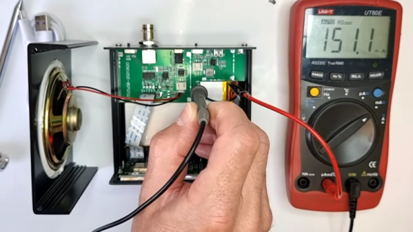
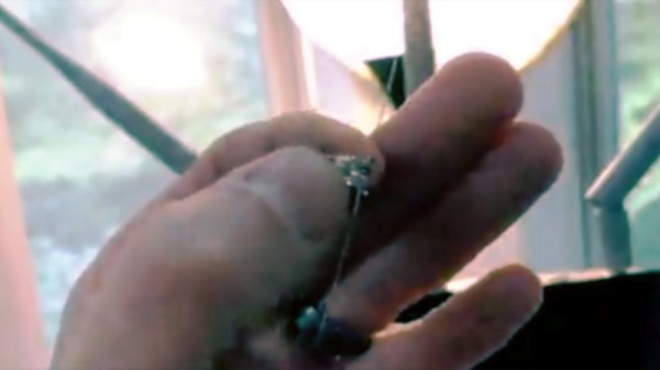
It’s about as simple as it gets, an LED with a UHF diode in reverse across it. The clever part lies in the wire leads, which are cut to resonate as a dipole at 2.4 GHz. The resulting RF voltage is rectified by the UHF diode, leaving enough DC for the LED to flash. If you are wondering why the LED alone couldn’t do the job as a rectifier you would of course be on to something, however its much worse high frequency performance would make it not up to the job at this frequency.
The glory days of analogue broadcasting may now be in the past, but it’s still possible to have fun with a more conventional crystal radio. If you are adventurous, you can even make one that works for the FM, band too.