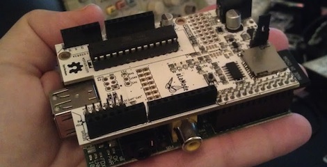
Raspberry Pi Power Regulator Transplant Reduces Power Consumption

If you want to run your Raspberry Pi from something other than a mains power converter, and you’ve got some courage to spare, this hack is right up your alley. [Tom] wrote in with a switch mode power replacement for the RPi’s stock linear regulator. This is the first hack we’ve seen where the RPi’s on-board hardware is being altered and that’s where things get a little scary.

The first thing done was to remove the linear regulator, leaving the unpopulated RG2 footprint seen above. Apparently a rework station wasn’t available as the technique they used describes holding the board up by gripping the regulator with tweezers, then blasting it with a hot air gun. It makes us a bit queasy because the processor chip has a solder footprint you don’t want to mess with.

But apparently all is still well. With the wasteful linear regulator gone a pair of 5v and 3.3V switch regulators inject voltage through the GPIO header. Initial tests show a savings of around 25% but we’d imaging this varies greatly based on load.

Raspberry Pi Enclosure Turns It Into A Desktop PC

While you’re still waiting for your Raspberry Pi to be delivered, why not build an enclosure for it? This build comes from the fruitful workshop of [builttospec], and gives the Raspi a very nice case well-suited for being placed on your desktop.

Like most of [builttospec]’s case builds, this enclosure was made on a laser cutter out of acrylic and features everything you would expect in a good Raspi enclosure. All the hardware ports are available, and there’s also a slot for a GPIO ribbon cable, perfect for connecting an enclosed Raspi to whatever hardware project you’re working on.

One thing we’re loving about [builttospec]’s enclosure is the tasteful use of light pipes that funnel the light from the LED indicators on the Raspi to the surface of the case. Sure, they’re just a few bits of laser-cut polycarbonate, but its little touches like this that transform a good case build into a great one.

Files available on Thingiverse.

Linux Picture Frame Serves As Wireless Raspberry Pi Display

Here’s a novel approach to adding a display to your Raspberry Pi. Instead of using a wired display — either via the HDMI (which can feed a DVI port with a simple hardware adapter) or the composite video out — [Chris Bryden] decided to use Bluetooth to provide a wireless display. This really depends on the hardware that you have available. He snapped up a hackable digital picture frame for a song and used the 320×240 display for this project.

You can see the USB nub plugged into the RPi in the image above. It’s a Bluetooth dongle and there’s with a matching one on the digital frame. With the two networked in such a way [Chris] got to work setting up a VNC that would let him pull up the X desktop over the network.

This ends up being one of the best uses we’ve seen for the Bluetooth protocol, and the small screen offers a huge advantage over the use of a simple character display.

Using An HD44780 Character LCD With The Raspberry Pi

[Tech2077] is one of the lucky ones who already got his hands on a Raspberry Pi. He’s been looking into different interface options with the GPIO header and just posted a guide to using an HD44780 character display with the RPi. We like this approach because instead of doing some hard-core LCD work he’s using prototyping equipment you probably already have on hand.

Getting a character LCD running should be really simple. The gotcha is the logic level gap between the devices. If you’ve been working with Arduino, your add-ons are probably meant for a 5V power rail  and logic levels. The RPi outputs 3.3V logic. You could use a level converter (you’d need at least 7 pins to be converted in this case) or you can be a bit more clever. [Tech2077] grabbed an I2C port expander that uses just 2 of the RPi lines to address even lines of the display (four data bits plus three control bits). This is a bit of a hack, as the 3.3V logic is 0.2V below the recommended minimum for a digital 1 on the port expander. But it seems to work just fine! If it didn’t, a couple of NPN transistors would do the trick as well.

Addressing the new peripheral is just a matter of loading the i2c module and writing some Python.

Penetration Testing With The Raspberry Pi

PwnPi is a penetration testing distribution rolled up for the Raspberry Pi platform. This should come as no surprise to anyone. The RPi board has a beefy processor, it’s relatively low power, has the option of the on-board NIC or a USB WiFi dongle, and it already has Linux kernel and desktop sources available to start from.

Now we will admit we’re a bit disappointed from this tip. Don’t get us wrong, the distro looks like it’s well done, and we’re sure there are a lot of folks out there who will be happy to have these tools to help test their network security. But this is a software only hack and we were expecting to see a nice little covert package that could be plugged into an outlet (SheevaPlug style), or a battery-powered module that can be plugged into an Ethernet port and hidden away.

Now you know what we want, don’t forget to send in a link once you pull it off.

[Thanks Scott]

Adding Heat Sinks To A Raspberry Pi

[Michael Dornisch] was surprised to find that the main processor of the Raspberry Pi reaches about 56 degrees Celsius (about 133 degrees F) while streaming video over the network. He thought it might help the longevity of the device if he was able to cool things off a bit. But why stop with just the processor? He added heat sinks to the SoC, Ethernet/USB chip, and voltage regulator.

From his parts bin he grabbed a small heat sink that was probably used on a graphics card. After measuring the three chips with his digital calipers he cut out the footprint he needed, resulting in three smaller heat sinks. We didn’t realize that thermal compound has enough gripping power to hold the sinks in place without any mechanical fastener, but apparently it does. [Michael] mentions that it’s possible to use other adhesives, like JB Weld. What’s important is that you use something (ie: thermal compound or a liquid adhesive) to prevent any air gap from coming between the chip surface and the aluminum.

He measured the result as a 17.3 degree C (31 degree F) drop in temperature. We looked around and it seems there’s no internal temperature sensor on the Broadcom chip so these surface readings will have to suffice. Do you think this will prolong the life of the board if it is used regularly to play back high quality video? We already know that these temperatures are within the specifications for the hardware.

[Thanks Simon]

Building Better Cases With A Laser Cutter

[Ryan] just got his Raspberry Pi, and what better way to add a new toy to your workbench than by building a case for it? Using a laser cutter and 3D printer, [Ryan] managed to make a case that is sure to be the envy of all the other tinkerers at his hackerspace.

The build started off with a piece of dark red acrylic in a laser cutter. After cutting the Raspberry Pi logo out of this acrylic, [Ryan] cut the same logo – a little bit larger – out of plywood. Because he was very careful to measure the kerf (or the width of the laser beam/saw blade/what have you), the wooded version of the Raspi logo fit snugly inside the acrylic cut out.

The sides of the enclosure are a single piece of plywood with a kerf bend, making for a very attractive rounded case. Finally, the Raspberry Pi is mounted on a Pi plate printed on a Ultimaker.

For as many builds we see using a laser cutter here on Hackaday, there’s surprisingly little information on exploiting the true potential of these machines with marquetry, intarsia, or fretwork. Enclosures are always cool, so if you have a very elegant laser cut box, send it in and we’ll put it up.