The Raspberry Pi’s venerable 40-pin header and associated HAT ecosystem for upgrades has been a boon for the platform. It’s easy to stack extra hardware on to a Pi, even multiple times in some cases. However, if you want to run multiple HATs, and wirelessly at that, the PiSquare might just be the thing for you.
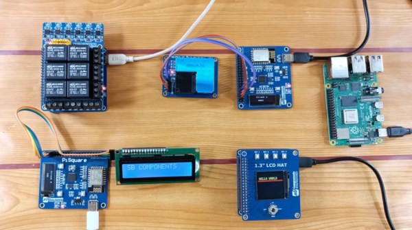
The PiSquare consists of a board featuring both RP2040 and ESP-12E microcontrollers. It interfaces with Raspberry Pi HATs and even lets you run multiple of the same HAT on a single Raspberry Pi, as it’s not actually directly using the UART, SPI, or I2C interfaces on the host Pi itself. Instead, the PiSquare communicates wirelessly with the Pi, handling the IO with the HAT itself.
It’s unclear how this works on a software level. Simply using existing software tools and libraries for a given Raspberry Pi HAT probably won’t work with the wireless PiSquare setup. However, for advanced users, it could serve a useful purpose, allowing one Raspberry Pi to command multiple HATs without the fuss of having to run more single-board computers where just one will do. Boards will be available on Kickstarter for those interested in the device.
We’ve seen other creative things done with the Raspberry Pi and the HAT system, too. If you’ve been cooking up your own neat hacks for the platform, drop us a line!