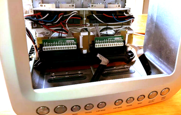
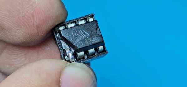
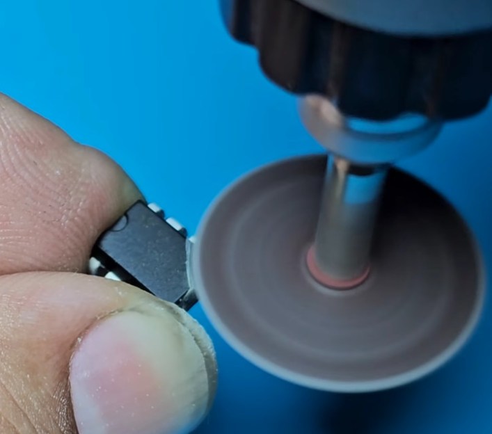
Showing a RAM chip being removed from a Pi 4 board, hot air gun in the shot. Area around the chip is covered with kapton tape.

Upgrade RAM On Your Pi 4, The Fun Way

The Raspberry Pi shortage has been a meme in hacker circles for what feels like an eternity now, and the Pi 4 seems to be most affected – though, maybe it’s just its popularity. Nevertheless, if you’re looking for a Pi 4, you would need to look far and wide – and things are way worse if you need the 8 GB version specifically. Or so we thought – [MadEDoctor] shows us that refreshing online store pages isn’t the only way, having successfully upgraded the RAM chip on the Pi 4 from 1 GB to 8 GB with help of a hot air gun.

These chips are BGA, and those might feel intimidating if you’re just starting out with hot air – however, we recommend you watch this video, as [MadEDoctor]’s approach is of the kind that brings BGA replacement to hobbyist level. First off, you get a compatible RAM chip somewhere like Aliexpress – lucky for us, those come equipped with a set of balls from the factory. The default balls are made of lead-free solder, and [MadEDoctor] reballed the RAM chip with leaded solder balls to lower the melting point, but it’s by no means a requirement that you do the same.

In fact, you only need a hot air gun, flux, a soldering iron and some solder wick to perform the replacement – no reballing equipment. Put some kapton or metal tape on the board for heat shielding, get the old chip off with hot air, use an iron with wick to clean the pads, add some flux, align the chip, then use hot air to solder a new chip onto the board. Replacing this chip can get your Pi 4 to the highly-sought-after 8 GB target – as an aside, we’re surprised that there was no configuration needed, as the Pi 4 booted right up and successfully recognized the extra RAM added.

We’d personally recommend preheating for such an upgrade – that said, this sure went without a hitch, and such a RAM swap method doesn’t require any stencils, solder paste or solder ball applications. Drop by the video description for compatible RAM chip part numbers, make sure you have your tacky flux and solder wick in order, and let [MadEDoctor] walk you through upgrading your Pi 4 the hacker way. Is this hack to your liking? Take it up a notch with this laptop soldered-in RAM upgrade journey, or that one RAM upgrade for an old GPU to comply to Apple’s whims.

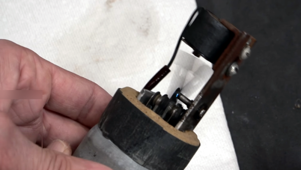
A closeup of the faulty section of the dial - you can spot the plastic rivets that broke off

The Tale Of Two Broken Flukes

Some repairs happen as if by pure luck, and [Sebastian] shows us one such repair on Hackaday.io. He found two Fluke 175 meters being sold on eBay, with one having a mere beeper issue, and another having a “strange error”. Now, theoretically, swapping beepers around would give you one working meter and a kit of spare parts – but this is Fluke we’re talking about, and [Sebastian] wasn’t satisfied leaving it there.

First, he deduced that the beeper issue could be fixed by repositioning the piezo disk – and indeed, that brought the meter number one to working order. This left the mysterious error – the meter would only power up in certain rotations of the dial, and would misbehave, at that. Disassembly cleared things up – the dial mechanics failed, in that a half of the metal contacts came detached after all the plastic rivets holding the metal piece in place mysteriously vanished. The mechanics were indeed a bit intricate, and our hacker hoped to buy a replacement, but seeing the replacement switch prices in three-digit range, out came the epoxy tube.

An epoxy fix left overnight netted him two perfectly working Fluke meters, and while we don’t know what the listing price was for these, such a story might make you feel like taking your chances with a broken Fluke, too. The tale does end with a word of caution from [Sebastian], though – apparently, cleaning the meters took longer than the repairs themselves. Nevertheless, this kind of repair is a hobbyist’s dream – sometimes, you have to design a whole new case for your meter if as much as a wire breaks, or painstakingly replace a COB with a TQFP chip.

Fixing A Reflow Oven’s Conveyer Belt With An NE555 And Stepper Motors

Some design choices on manufacturing equipment really leave you scratching your head for a while, as recently happened to [Chris Cecil] when the belt on a reflow oven’s conveyer snapped. Although the solution seems simple enough, getting a new belt on the thing would involve essentially taking the entire machine apart, before reassembling it again. Thus the frayed belt went through the oven over and over until during a recent production run of Smoothieboard controller boards until [Chris] heard a funny noise and the conveyer ground to a halt.

Moving the conveyer by hand kind of worked, but with a more permanent fix urgently needed to finish the production run, two stepper motors took the place of the belt, which just left driving these steppers to keep the conveyer moving in sync. Lacking a simple Arduino board to toss at it, and with a Smoothieboard being absolute overkill, [Chris] figured that a humble NE555 timer IC ought to do the job just as well.

Using a project on Hackaday.io by [KushagraK7] as the starting point, and a 1992-vintage NE555 IC harvested from an old project, [Chris] managed to put together a basic stepper driver that uses the NE555 to provide the timing signal. In addition to restoring basic functionality like starting and stopping the conveyer belt, [Chris] added a new feature with the reversing of the conveyer direction. Along with some cobbled together components to physically rotate the conveyer’s two rollers, it restored the reflow oven to working condition.

And one day the prototyped driver board will be updated to a proper PCB. It’s only temporary, after all :)

Continue reading “Fixing A Reflow Oven’s Conveyer Belt With An NE555 And Stepper Motors”

A closeup of a black flexible PCB with an out-of-focus quarter in the background, approximately the same size as the end of the PCB we're looking at. One the right is a USB C connector and to its left are two SMD components with visible pins. Several smaller SMD components (resistors or caps?) are soldered to other parts of the board.

Making The AirPods Pro Case Repairable

Apple is often lauded for its design chops, but function is often sacrificed at the altar of form, particularly when repair is involved. [Ken Pillonel] has made it easier for everyone to replace the batteries or lightning port in the AirPods Pro case. (YouTube)

With such notable hacks as adding USB C to the iPhone already under his belt, [Pillonel] has turned his attention to fixing the notoriously poor repairability of AirPods and AirPods Pro, starting with the cases. While the batteries for these devices are available, replacement Lightning ports are not, and taking the housing apart for the case is an exercise in patience where the results can’t be guaranteed.

He designed a USB C replacement port for broken Lightning ports that is a perfect fit if you happen to get the case apart in one piece. If you’re less successful, he has you covered there too with a 3D printable enclosure replacement.

We sure miss the days of schematic proliferation here at Hackaday, but we know you don’t let glued enclosures or unobtainium parts stand in the way of repairs.

Continue reading “Making The AirPods Pro Case Repairable”

Picture of a DualShock 4 controller PCB, with two joysticks on the sides

Challenging A Broken DualShock 4 Controller To A Duel

A broken PlayStation controller would normally be a bummer, and if the issue is losing calibration that’s stored in a non-documented format, you might as well bin it. For [Al] of [Al’s blog], however, it’s a challenge, turning into a four-part story – so far. The first installment was published January 1st this year, and seeing the pure enthusiasm [Al] has reverse-engineering the DualShock 4 controller, you might guess that this is a New Year’s gift from someone who knows [Al] very well. The list of problems with the joystick is numerous, to begin with – it’s easier to list all the things that work properly, and it isn’t many of them. Perhaps, the firmware problem is is the most interesting one to start with. Continue reading “Challenging A Broken DualShock 4 Controller To A Duel”

Dishwasher Repair Nightmare: Chasing Down 3 Faults

It all started with a vague error code (shown in the image above) on [nophead]’s Bosch SMS88TW01G/01 dishwasher, and it touched off a months-long repair nightmare that even involved a logic analyzer. [nophead] is normally able to handily diagnose and repair electronic appliances, but this time he had no idea what he was in for.

Not many dishwashers require breaking out a logic analyzer and 3D-printed custom adapters, but this one did.

Not only were three separate and unrelated faults at play (one of them misrepresented as a communications error that caused a lot of head-scratching) but to top it all off, the machine is just not very repair-friendly. The Bosch device utilized components which are not easily accessible. In the end [nophead] prevailed, but it truly was a nightmare repair of the highest order. So what went wrong?

One error appears to have been due to a manufacturing problem. While reverse-engineering the electronics in the appliance, [nophead] noticed a surface-mounted transistor that looked crooked. It was loose to the touch and fell into pieces when he attempted to desolder it. This part was responsible for switching an optical sensor, so that was one problem solved.

Another issue was a “communications error”. This actually came down to ground leakage due to a corroded and faulty heater, and to say that it was a pain to access is an understatement. Accessing this part requires the machine to be turned upside down, because the only way to get to it is by removing the base of the dishwasher, which itself requires a bizarre series of awkward and unintuitive steps to remove. Oh, and prior to turning the machine upside down, one has to purge the sump pump, which required a 3D-printed adapter… and the list goes on.

And the E02 error code, the thing that started it all? This was solved early in troubleshooting by changing a resistor value by a tiny amount. [nophead] is perfectly aware that this fix makes no sense, but perhaps it was in fact related to the ground leakage problem caused by the corroded heater. It may return to haunt the future, but in the meantime, the machine seems happy.

It goes to show that even though every fault has a cause and a reason, sometimes they are far from clear or accessible, and the road to repair is just a long slog. Heck, even phones these days can be bricked by accidentally swapping a 1.3 mm screw for a 1.2 mm screw.

Fixing An HP 54542C With An FPGA And VGA Display

Although the HP 54542C oscilloscope and its siblings are getting on in years, they’re still very useful today. Unfortunately, as some of the first oscilloscopes to switch from a CRT display to an LCD they are starting to suffer from degradation. This has led to otherwise perfectly functional examples being discarded or sold for cheap, when all they need is just an LCD swap. This is what happened to [Alexander Huemer] with an eBay-bought 54542C.

Although this was supposed to be a fully working unit, upon receiving it, the display just showed a bright white instead of the more oscilloscope-like picture. A short while later [Alexander] was left with a refund, an apology from the seller and an HP 54542C scope with a very dead LCD. This was when he stumbled over a similar repair by [Adil Malik], right here on Hackaday. The fix? Replace the LCD with an FPGA and VGA-input capable LCD.

While this may seem counter intuitive, the problem with LCD replacements is the lack of standardization. Finding an 8″, 640×480, 60 Hz color LCD with a compatible interface as the one found in this HP scope usually gets you salvaged LCDs from HP scopes, which as [Alexander] discovered can run up to $350 and beyond for second-hand ones. But it turns out that similar 8″ LCDs are found everywhere for use as portable displays, all they need is a VGA input.

Taking [Adil]’s project as the inspiration, [Alexander] used an UPduino v3.1 with ICE40UP5K FPGA as the core LCD-to-VGA translation component, creating a custom PCB for the voltage level translations and connectors. One cool aspect of the whole system is that it is fully reversible, with all of the original wiring on the scope and new LCD side left intact. One niggle was that the scope’s image was upside-down, but this was fixed by putting the new LCD upside-down as well.

After swapping the original cooling fan with a better one, this old HP 545452C is now [Alexander]’s daily scope.