Interposer Helps GPS Receiver Overcome Its Age

We return to [Tom Verbeure] hacking on Symmetricom GPS receivers. This time, the problem’s more complicated, but the solution remains the same – hardware hacking. If you recall, the previous frontier was active antenna voltage compatibility – now, it’s rollover. See, the GPS receiver chip has its internal rollover date set to 18th of September 2022. We’ve passed this date a while back, but the receiver’s firmware isn’t new enough to know how to handle this. What to do? Build an interposer, of course.

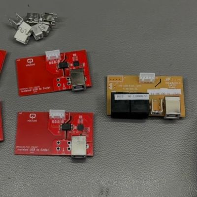
You can bring the module up to date by sending some extra init commands to the GPS chipset during bootup, and, firmware hacking just wasn’t the route. An RP2040 board, a custom PCB, a few semi-bespoke connectors, and a few zero-ohm resistors was all it took to make this work. From there, a MITM firmware wakes up, sends the extra commands during power-on, and passes all the other traffic right through – the system suspects nothing.

Everything is open-source, as we could expect. The problem’s been solved, and, as a bonus, this implant gives a workaround path for any future bugs we might encounter as far as GPS chipset-to-receiver comms are concerned. Now, the revived S200 serves [Tom] in his hacking journeys, and we’re reminded that interposers remain a viable way to work around firmware bugs. Also, if the firmware (or the CPU) is way too old to work with, an interposer is a great first step to removing it out of the equation completely.

A stainless steel metal toaster sits on a white table. Its cord is draped artfully around to the front and the leftmost toast holding apparatus is rotated out from the front of the device like a book pulled down and out from a bookshelf.

Flat Pack Toaster Heats Up The Right To Repair

The toaster is a somewhat modest appliance that is often ignored until it stops working. Many cheap examples are not made to be easily repaired, but [Kasey Hou] designed a repairable flat pack toaster.

[Hou] originally planned to design a repairable toaster to help people more easily form an emotional attachment with the device, but found the process of disassembly for existing toasters to be so painful that she wanted to go a step further. By inviting the toaster owner into the process of assembling the appliance, [Hou] reasoned people would be less likely to throw it out as well as more confident to repair it since they’d already seen its inner workings.

Under the time constraints of the project, the final toaster has a simpler mechanism for ejecting toast than most commercial models, but still manages to get the job done. It even passed the UK Portable Appliance Test! I’m not sure if she’d read the IKEA Effect before running this project, but her results with user testing also proved that people were more comfortable working on the toaster after assembling it.

It turns out that Wikipedia couldn’t tell you who invented the toaster for a while, and if you have an expensive toaster, it might still be a pain to repair.

Close up of Zenit 19 camera

Behind The Lens: Tearing Down A Rare Soviet Zenit 19

If you’re into Soviet-era gear with a techy twist, you’ll love this teardown of a rare Zenit 19 camera courtesy of [msylvain59]. Found broken on eBay (for a steal!), this 1982 made-in-USSR single-lens reflex camera isn’t the average Zenit. It features, for example, electronically controlled shutter timing – quite the upgrade from its manual siblings.

The not-so-minor issue that made this Zenit 19 come for cheap was a missing shutter blade. You’d say – one blade gone rogue! Is it lost in the camera’s guts, or snapped clean off? Add to that some oxidized battery contacts and a cracked viewfinder, and you’ve got proper fixer-upper material. But that’s where it gets intriguing: the camera houses a rare hybrid electronic module (PAPO 074), complete with epoxy-covered resistors. The shutter speed dial directly adjusts a set of resistors, sending precise signals to the shutter assembly: a neat blend of old-school mechanics and early electronics.

Now will it shutter, or stutter? With its vertical metal shutter – uncommon in Zenits – and separate light metering circuitry, this teardown offers a rare glimpse into Soviet engineering flair. Hungry for more? We’ve covered a Soviet-era computer and a radio in the past. If you’re more into analog camera teardowns, you might like this analog Pi upgrade attempt, or this bare minimum analog camera project.

Continue reading “Behind The Lens: Tearing Down A Rare Soviet Zenit 19”

LCD Stackup Repair: Not For The Faint Of Heart

Coming straight to the point: [Ron Hinton] is significantly braver than we are. Or maybe he was just in a worse situation. His historic Acer K385s laptop suffered what we learned is called vinegar syndrome, which is a breakdown in the polarizers that make the LCD work. So he bit the bullet and decided to open up the LCD stack and replace what he could.

Nothing says “no user serviceable parts inside” quite like those foil-and-glue sealed packages, but that didn’t stop [Ron]. Razor blades, patience, and an eye ever watchful for the connectors that are seemingly everywhere, and absolutely critical, got the screen disassembled. Installation of the new polarizers was similarly fiddly.

In the end, it looks like the showstopper to getting a perfect result is that technology has moved on, and these older screens apparently used a phase correction layer between the polarizers, which might be difficult to source these days. (Anyone have more detail on that? We looked around and came up empty.)

This laptop may not be in the pantheon of holy-grail retrocomputers, but that’s exactly what makes it a good candidate for practicing such tricky repair work, and the result is a readable LCD screen on an otherwise broken old laptop, so that counts as a win in our book.

If you want to see an even more adventurous repair effort that ended in glorious failure, check out [Jan Mrázek]’s hack where he tries to convert a color LCD screen to monochrome, inclusive of scraping off the liquid crystals! You learn a lot by taking things apart, of course, but you learn even more by building it up from first principles. If you haven’t seen [Ben Krasnow]’s series on a completely DIY LCD screen, ITO-sputtering and all, then you’ve got some quality video time ahead of you.

How To Find Where A Wire In A Cable Is Broken

Determining that a cable has a broken conductor is the easy part, but where exactly is the break? In a recent video, [Richard] over at the Learn Electronics Repair channel on YouTube gave two community-suggested methods a shake to track down a break in a proprietary charging cable. The first attempt was to run a mains power detector along the cable to find the spot, but he didn’t have much luck with that.

The second method involved using the capacitance of the wires, or specifically treating two wires in the cable as the electrodes of a capacitor. Since the broken conductor will be shorter, it will have less capacitance, with the ratio theoretically allowing for the location of the break in the wire to be determined.

In the charging cable a single conductor was busted, so its capacitance was compared from both sides of the break and compared to the capacitance of two intact conductors. The capacitance isn’t much, on the order of dozens to hundreds of picofarads, but it’s enough to make an educated guess of where the rough location is. In this particular case the break was determined to be near the proprietary plug, which ruled out a repair as the owner is a commercial rental shop of e-bikes.

To verify this capacitor method, [Richard] then did it again on a piece of mains wire with a deliberate cut to a conductor. This suggested that it’s not a super accurate technique as applied, but ‘good enough’. With a deeper understanding of the underlying physics it likely can be significantly more accurate, and it’s hardly the only way to find broken conductors, as commentators to the video rightly added.

Continue reading “How To Find Where A Wire In A Cable Is Broken”

Fixing a hoodie zipper with a drinking straw and hot glue.

Hack That Broken Zipper!

We’ve all been there. That sad day when the zipper on our favorite hoodie, bag, or pair of pants breaks in some seemingly irreparable way. But there is hope, and [Magic Stitches] is gonna show you how to make some common repairs using household items and, in some cases, just a little bit of easy hand sewing. After a warm up with a kitchen fork, the video moves on to more significant problems.

The first problem — a chewed-away zipper bottom — is quite common, but requires no sewing to fix. As you’ll see in the video below, all it takes is a drinking straw, some hot glue, a lighter, and a pair of scissors to recreate the plastic bit that keeps the zipper from splitting in twain.

Sewing the teeth of a zipper together after cutting the tape just enough to slide the head back on. Now the second issue concerns a pair of pants wherein the head has come off the static side of the zipper. This one seems impossible to fix, but [Magic Stitches] cuts into the static side about five teeth from the bottom, slides the head back on, and sews the bottom of the zipper together.

This one we take a little bit of an issue with, because it assumes that you can get your jeans on over your hips without needing the zipper head to be fully down. But what else are you going to do but throw the jeans away upcycle the jeans into a fanny pack or something to immortalize them?

Continue reading “Hack That Broken Zipper!”

Repairing An Old Heathkit ‘Scope

With so many cheap oscilloscopes out there, the market for old units isn’t what it used to be. But if you have a really old scope, like the Heathkit O-10 that [Ken] found in his basement, there is vintage cred to having one. [Ken’s] didn’t work, so a repair session ensued. You can see the results in the video below.

You can tell this is in an old scope — probably from the mid 1950s — because of its round tube with no graticle. Like many period scopes, the test probe input was just 5-way binding posts. The O-10 was the first Heathkit “O-series” scope that used printed circuit boards.

The device looked pretty good inside, except for a few dents. Of course, the box has tubes in it, so every power up test involves waiting for the tubes to warm up. [Ken] was very excited when he finally got a single green dot on the screen. That did, however, require a new CRT.

It wasn’t long after that he was able to put a waveform in and the scope did a good job of reproducing it. The unit would look good in an old movie, but might not be the most practical bench instrument these days.

These Heathkit scopes and their cousins were very popular in their day. The $70 price tag sounds cheap, but in the mid-1950s, that was about a month’s rent in a four-room house. While primitive by today’s standards, scopes had come a long way in 9 or 10 years.

Continue reading “Repairing An Old Heathkit ‘Scope”