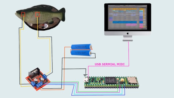
We’re big fans of useless machines here at Hackaday, there’s something undeniably entertaining about watching a gadget flail about dramatically without actually making any progress towards a defined goal. But what happens when one of these meme machines ends up working too well? We think that’s just what we might be witnessing here with the Tacobot from [Vije Miller].
On the surface, building an elaborate robotic contraption to (slowly) produce tacos is patently ridiculous. Doubly so when you tack on the need to give it voice commands like it’s some kind of one-dish version of the Star Trek food replicator. The whole thing sounds like the setup for a joke, an assumption that’s only reinforced after watching the dramatized video at the break. But in the end, we still can’t get over how well the thing appears to work.
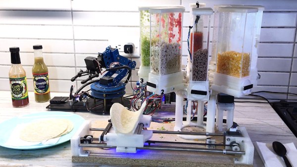
 After [Vije] gives it a list of ingredients to dispense, a robotic arm drops a tortilla on a fantastically articulated rotating platform that can not only spin and move in two dimensions, but can form the soft shell into the appropriate taco configuration. The empty shell is then brought under a rotating dispenser that doles out (or at least attempts to) the requested ingredients such as beef, onions, cheese, and lettuce. With a final flourish, it squirts out a few pumps of the selected sauce, and then presents the completed taco to the user.
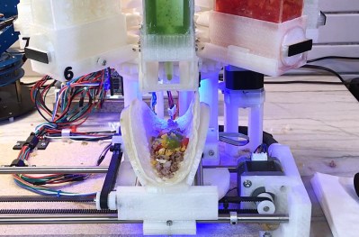
The only failing appears to be the machine’s ability to dispense some of the ingredients. The ground beef seems to drop into place without issue, but it visibly struggles with the wetter foodstuffs such as the tomatoes and onions. All we know is that if a robot handed us a taco with that little lettuce on it, we’d have a problem. On the project page [Vije] acknowledges the issue, and says that a redesigned dispenser could help alleviate some of the problem.
The issue immediately brought to mind the fascinating series of posts dedicated to handling bulk material penned by our very own [Anne Ogborn]. While the application here might be a bit tongue-in-cheek, it’s still a perfect example of the interesting phenomena that you run into when trying to meter out different types of materials.
Continue reading “An Impressively Functional Tacobot” →