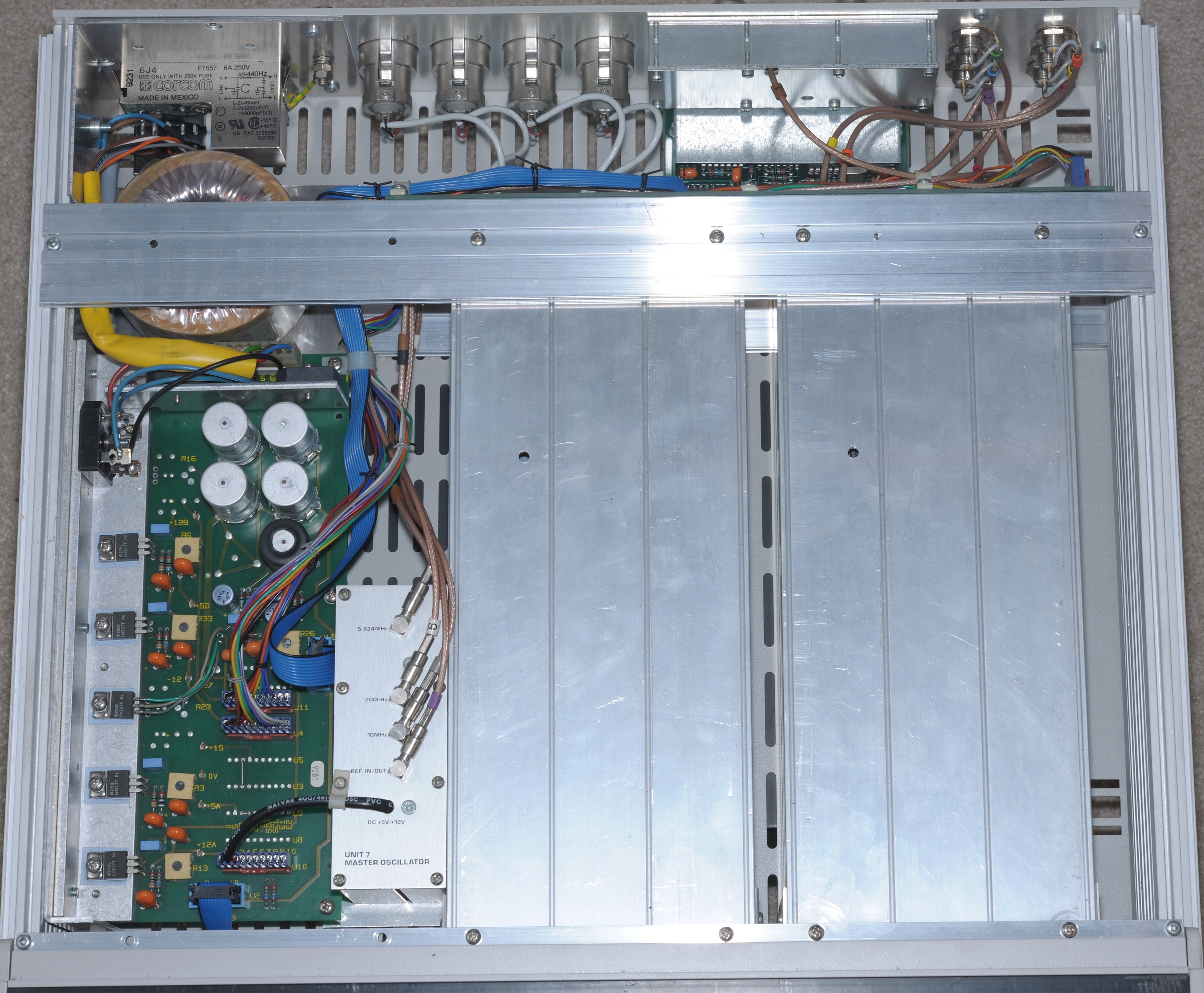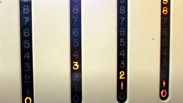
We think of digital displays as something you see on relatively modern gear. But some old gear had things like nixies or numitrons to get cool-looking retro digital displays. The HP 521A frequency counter, though, uses four columns of ten discrete neon bulbs to make a decidedly low-tech but effective digital display. [Usagi Electric] has been restoring one of these for some time, but there was a gap between the second and third videos as his workshop became a kitten nursery. You can see the last video below.
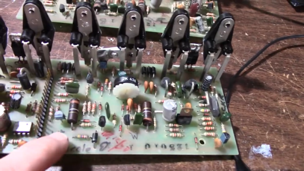
In previous videos, he had most of the device working, but there were still some odd behavior. This video shows the final steps to success. One thing that was interesting is that since each of the four columns are identical, it was possible to compare readings from one decade to another.
However, in the end, it turned out that the neon bulbs were highly corroded, and replacing all the neon bulbs made things work better. However, the self-check that should read the 60 Hz line frequency was reading 72 Hz, so it needed a realignment. But that was relatively easy with a pot accessible from the back panel. If you want to see more details about the repair, be sure to check out the earlier videos.
We love this old gear and how clever designers did so much with what we consider so little. We hate to encourage your potential addiction, but we’ve given advice on how to acquire old gear before. If you want to see what was possible before WS2812 panels, you could build this neon bulb contraption.
Continue reading “Frequency Counter Restoration Impeded By Kittens”