A good multimeter (or a few of them) is an essential part of anyone’s electronics workbench. The only thing more useful than a multimeter is a logging multimeter that can take recordings over time. And the only thing more useful than that is one that can transfer that data back to your computer for analysis. But fancy meters often cost a bit of money.
[Kerry Wong] decided to take matters into his own hands and hack a serial-out port into his relatively inexpensive multimeter, giving him the ability to record anything the meter can measure roughly three times a second until he runs out of hard-drive space.
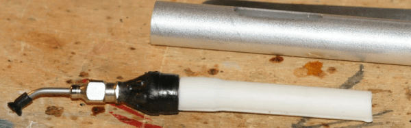
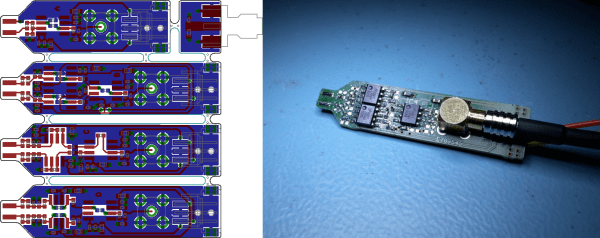
Our hack begins with the datasheet for the meter’s microprocessor. [Kerry] then tacked on a few wires, and dumped, modified, and reflashed the calibration and configuration EEPROM. With a single bit-flip in the EEPROM, he enabled serial output. With a few more, he made the backlight stay on longer, disabled auto power-off, and basically customized the meter the way he wanted it.
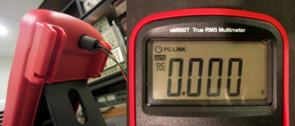
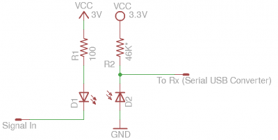 Getting the data out of the meter is the big coup, however. Not wanting to risk the computer that he’s connecting to the meter, [Kerry] knew that he needed optoisolation between the meter and the USART. He went with a beautifully minimal solution — simply wiring the meter’s serial output to an IR LED. Usually, transmitting data over IR is done by modulating the signal with a 38 kHz carrier for noise immunity. [Kerry] was going to put the receiver right up against the transmitter anyway, so he went with a plain IR photodiode on the PC side. sigrok takes care of the datalogging and display.
Adding more automation to our measurement bench has been on our to-do list for a long time now, and [Kerry]’s hack provides an inexpensive and fun way to get started. It’s the perfect companion to a computer-controlled supply. (Or two!.)