PCB Drill From R/C Car Parts

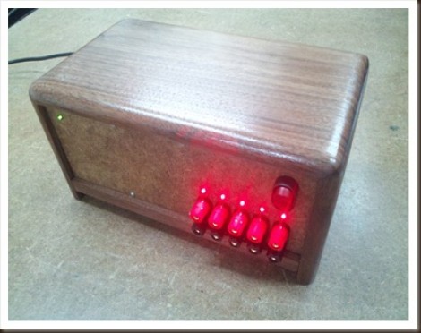
[Sid] makes a few PCBs a month and the hardest part of his fabrication process is always drilling the through-holes. He has a PCB hand drill that usually results in a sore index finger. After a few unsuccessful attempts of using a full-size electric drill and not wanting to invest in a commercial solution, [Sid] made a PCB drill from a broken R/C car.

The toy car was donated by [Sid]’s 4-year-old after a terrible crash. [Sid] took the gearbox from the car and added a small circuit to control the direction of the drill. After attaching the drill chuck to the former R/C car axle and adding the power leads to a 5 Volt adapter, a PCB drill press was born.

Most of the parts for this build were salvaged from the toy car’s radio control circuit. Except for the chuck from [Sid]’s hand drill and a few switches, everything on this build was pulled from a broken remote control car. While the build is a lot simpler than this semi-automatic PCB drill, [Sid]’s drill seems to work well. Check out the demo video after the break.

Continue reading “PCB Drill From R/C Car Parts”

Improving Your Welder Without A Microcontroller

We’re always impressed when a piece of hardware is torn apart, rebuilt and ends up exceeding the capabilities of the original device. [Dave] and [Will]’s home-built TIG welder is no exception to that rule.

When [Dave] and [Will] started working on converting a simple AC stick welder to a welder with every function imaginable, they decided to keep it simple. After looking at some high-price commercial welders they came up with a list of features they wanted to have and decided to implement this in TTL and CMOS logic. The guys didn’t want to go with a microcontroller solution because not everyone can code, and discrete chips are very easy to troubleshoot given minimal tools.

For the high voltage part of the build, the original flyback transformer was replaced with a neon sign transformer and homebrew spark gap and capacitor. The plans for a homebrew spark gap and cap didn’t quite work out so they were replaced with commercial units. The guys included schematics and a PCB layout (PDF warning) of their build. It’s always great to see an amazing logic chip build, and improving an existing tool never hurts.

Thanks to [Franci] for sending this one in.

Adding Fluke 54 II Features To A 51 II Thermometer

The difference between Fluke’s 54 II and 51 II thermometers is the addition of a second channel for dual temperature sensing, and buttons which control data logging. Oh, and an additional $150 in price for the higher model. [TiN] was poking around inside and with the help of some forum members he figured out how to unlock additional features on his low-end Fluke temperature meter. You can do the same if you don’t mind cracking open the meter, sourcing and soldering most of the components seen above, cutting holes in the case for the buttons, and hoping it still works when you put everything back together.

It seems that Fluke designed one full-featured unit and watered it down to fill a hole in the lower-priced market just like some other testing-hardware manufacturers (Rigol’s digital storage oscilloscopes come to mind). But the MSP430 P337I in this meter cannot be reflashed, so this would most likely be unhackable hardware if the firmware for the two models is different. After some intensive study of the PCB layout [TiN] found a set of resistors which seemed to serve no external hardware purpose. They do connect to the microcontroller and together they create a two-bit code. He was able to get pictures of the four different hardware models and work out which resistor combinations identify the different meters. Now he can get the firmware to believe it is operating a Fluke 54 II, the rest is just putting the correct passive components onto the unpopulated locations.

We think the quest is what is of interest with this hack. [TiN] did an amazing job of photographing and writing about each step in the process. We’re unlikely to try this ourselves but loved reading about it.

DIY Portable Charger/generator

portable_charger_generator

[Glenn] from The Back Shed has built a lot of windmills and stationary generators over the years, but recently decided to try his hand at building something a bit more portable.

The charger is based of a relatively simple design, employing a 5.2 HP Kubota 4 stroke motor and a 12v car alternator to provide power. While you might be inclined to point out that his charger does exactly what an alternator and motor are built to do, there was a bit more to it than simply slapping the two parts together.

A laser cut adapter plate holds the motor and alternator together, but once [Glenn] wrapped things up and gave the motor a spin, he realized that he was driving the alternator backwards. This would eventually cause the alternator to overheat since the cooling fan was running the wrong way. He removed the fan and reversed the fins with a hammer so that he could get the cooling he needed without having to reinstall the alternator in the opposite orientation.

The whole kit was mounted on a hand truck for portability, and [Glenn] says that the charger/generator only needs to run about 5 minutes before a dead battery has enough juice to crank an engine.

[via HackedGadgets]

Engine Hacks: Electric Drill Made Into A Trolling Motor

We knew our engine hacks theme would come down to an argument over the difference between “a motor” and “an engine” so after much deliberation, name calling, restraining orders, and a duel we’re happy to put up [Berto]’s DIY trolling motor made out of an electric drill. The project is probably inspired by [Berto]’s collapsible amphibious e-scooter that used the same electric drill propulsion setup.

The build is just a few pieces of wood, drill rod, some hardware and a prop. Definitely not the most complicated build. This isn’t the speediest motor ever when attached to a canoe, and isn’t meant to be a primary means of propulsion. That’s not a problem for this build – trolling motors aren’t designed to be fast or powerful. There’s no word on how much thrust [Berto]’s motor can put out, but it is a nice bit of MacGyverism to build a boat motor out of spare parts.

Check out the build walk though video after the break to see the motor in action.

Continue reading “Engine Hacks: Electric Drill Made Into A Trolling Motor”

Salvaging A Commercial-grade Pick And Place Machine

Why build a pick and place machine from the ground up when you can start with a full featured, but non-functional unit, and bring it back to life. That’s exactly what [Charliex] is doing with this Juki 360 rebuild.

A bit of background is in order here. [Charliex] is working alongside other hackers at Null Space Labs to restore this hardware. The Los Angeles based hackerspace sponsored the hardware badges at this year’s LayerOne, each of which was hand assembled. They’d like to avoid that tedium next year, which led to this project.

The seller of the used Juki 360 listed it in working condition, but it seems that they were polishing a turd since it is basically non-functional. The link at the top of this post is the second testimonial of their work so far. It covers the use of an Arduino board as a replacement interface, as well as a bunch of sensor repair, pneumatic testing, and motor driver firmware tweaking. If you’d like to see the initial teardown and hardware diagnostics don’t miss the first post in their adventure.

Simple Transistor Tester Makes Sorting Easy

simple_transistor_sorter

Hacker [Dino Segovis] is back with yet another installment of his Hack a Week series, and it’s looking like he isn’t too worse for wear after hunkering down to face hurricane Irene.

This week, it seems that [Dino] is having some problems separating his PNP transistors from his NPNs. After Albert Einstein proves to be less than useful when it comes to sorting electronic components, [Dino] decided to build a simple transistor tester to help him tell his PNPs and NPNs apart without having to resort to looking up product data sheets.

The tester itself is relatively simple to build. As you can see in the video below, it consists of a power supply, an LED, a few resistors, a pair of known transistors, and not much else. When everything is hooked together, the NPN/PNP pair causes the LED to light up, but the circuit is broken whenever one of the transistors is removed. Inserting a new transistor into the empty spot on the breadboard immediately lets you know which sort of transistor you have inserted.

Sure you can tell transistors apart with a multimeter, but if you have a whole drawer full of loose components, this is a far more efficient option.

Continue reading “Simple Transistor Tester Makes Sorting Easy”