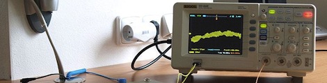
Beautifully Crafted Geiger Counter A Must If You Live In A Hot Zone

Have a little class when you’re screening for radioactive particles. You can follow the example which [Moustachenator] has set with this gorgeous Geiger counter case.

The business end includes the same Geiger tube we see in all of these projects, but he took the time to solder together a tidy circuit board and housed it in an acrylic tube. it connects to the base unit using a springy telephone handset cord. The laser cut walnut enclosure offers plenty of room for the ATX power supply hidden inside. This feeds the Arduino which runs the system, and provides a powerful source for the Nixie tubes which serve as the display. The attention to detail when it came time to assemble the case is what lends an antique look to the project, even though everything was built from the ground up. Check out the video after the break to see a brief demonstration.

Continue reading “Beautifully Crafted Geiger Counter A Must If You Live In A Hot Zone”

Scratch-built RFID Reader

We never bought an RFID reader because it seems too simple to be all that much fun. But [Abdullah] really caught our eye with his latest project. It’s an RFID reader built from discrete parts, and that’s an adventure we can get behind!

His write-up dives right into the theory of the device. He wrapped his own coil, which measure about one microhenry, then shares an equation used to calculate the appropriate capacitor pair for it. This is fed by a 125 kHz oscillator and works as the most basic reader. In practice this needs more components for rock-solid operation and he quickly moves to a marginally more complicated circuit which still does exactly the same thing.

He is now able to detect RFID tag data by reading this circuit with an oscilloscope. But the signal is very very weak. The rest of the post focuses on how to best utilize an OpAmp to increase signal quality and on/off time.

If you’re looking to recreate his reader [Abdullah] included a Kicad schematic and board layout.

Saving The ISS By Hacking A Toothbrush


We absolutely love these stories of hacker ingenuity saving peoples lives. In this case, it was aboard the ISS, and the item being hacked was a toothbrush.

The story is as follows. Some equipment failed, as space junk tends to do, and the astronauts found themselves needing to do some repairs. Upon inspection, they couldn’t remove some modules due to an accumulation of “space dust” around some bolts.  This was especially troubling as the unit in question was something that was supposed to route power from some of the solar arrays to the ISS. Even more troubling is that another unit failed while they were assessing the situation.

Realizing they had to act fast so as not to lose too much power to function, they cobbled together some tools to allow them to clean out the access ports and remove the units for repair. A task that sounds like an easy solution here on earth proved to be life threatening in space. Eventually though, their makeshift tools came to the rescue and they were able to repair and restore power.

Etching Your Own PCBs At Home

Etching your own PCBs from copper clad board is nothing new, but the ability to make your own circuit boards at home is so useful it should be part of every maker’s repertoire of skills. The folks over at Hub City Labs in Moncton, NB, Canada put together a workshop covering the basics of home PCB manufacturing, allowing any maker to put a circuit board in their hands in under an hour.

The process starts just like any PCB design – laying out traces, parts, and vias in a PCB designer such as Eagle. When making your own boards, it’s a good idea to make the traces and pads extra large; the folks at Hub City Labs follow the 50-50 rule: 50 mil wide traces with 50 mils of seperation.

The PCB design is printed out with a laser printer (in mirror mode) onto a piece of paper from a glossy magazine or inkjet photo paper. After the copper board is scrubbed to remove any oxidation or oils present, the design is laid face down on the copper and heated with a clothes iron or sent through a laminator.

After the laser printer toner is transferred to the copper, the recipe calls for etching the board with a solution consisting of a half cup of 3% Hydrogen Peroxide and a quarter cup of muriatic acid.

The folks at Hub City Labs put together a great tutorial for one of the most useful skills the home electronics wizard can have, but etching your own PCBs is an art unto itself. There’s a lot of ways this process can be improved, from using Kapton tape to secure the printed art to the copper board, to getting high-strength peroxide from a beauty supply store.

If you’ve got any tips on making your own PCBs at home, drop a line in the comments below.

EDIT: Good job killing Hub City Lab’s web server, everybody. They’re working on getting something up.

ARM-based Debugging Tool Aims To Improve On The Bus Pirate Performance

The Bus Pirate is a fantastic development tool. It does an amazing job at a lot of different things. And as it has matured, community support has driven it to new areas beyond the original design. This is where its hardware holds back performance a little bit. For instance, as an I2C or SPI sniffer it has limited capture speed. That’s the type of thing that this board could improve upon. It’s a debugging tool based on an STM32 F4 microcontroller. That’s an ARM Cortex-M4 chip which runs at 168 MHz, and has 192 KB of SRAM.

[TitanMKD] has been working on the design but it is still just in digital form. Since there’s no prototype there is also no firmware for the device. That’s a tall mountain to climb and it’s one of the reasons we’re featuring the project now. [Titan’s] plan is to model this after the Bus Pirate interface. We think it’s a good idea since a lot of folks have already learned the syntax. We didn’t see a contact form on his site, but if you’re interested in contributing to the project you might want to leave a comment here or on his project page (linked above).

Forget Treating Your Diabetes – Use Your Insulin Syringe As A Logic Probe

syringe-logic-probe

Hackaday reader [JumperOne] was in need of a logic probe that he could use to reliably test some tiny .5mm pitch IC pins. The probe that came with his oscilloscope was a bit too big and not near sharp enough to do the job, but he figured that a syringe might do the trick nicely.

He drilled a small hole near the business end of the syringe, through which he fed a piece of stripped twisted pair cabling. [JumperOne] then soldered a pair of pins to a small piece of coaxial cable, attaching the opposite end to the twisted pair already in the syringe. After carefully coiling the thin cable around the needle, he secured the coaxial cable and its pins in place with a bit of hot glue.

[JumperOne] says that his makeshift logic probe works very well and the sharp needle would easily pierce through any oxidation or solder mask that stands in its way. One extra benefit of using a syringe as a probe is that they come complete with caps which help protect both ends of the delicate tool.

BGA Soldering With A Paint Stripper And Stopwatch

Having just received a shiny set of PCBs from the fab-house [Devbisme] needed a way to solder the main chip in place. It has a Ball-Grid Array footprint which is notoriously difficult to populate in a home lab. But he makes it look pretty easy and decided to share a video tutorial of the process.

The main tool he used is the paint stripper (heat gun) seen above. Since he didn’t have his own fancy reflow oven he made things work with the gun as his heat source. First he applies a generous layer of liquid solder flux to the BGA footprint on the board. Next he melts some solder onto the tip of his iron and uses it to tin all of the board’s BGA pads. Then it’s time for the critical step of positioning the chip. He uses vacuum tweezers to set it in place, and traditional tweezers to fine-tune its position. From here he heats with the paint stripper for two minutes, starting far above the board and slowly moving closer, with the reverse at the end of the soldering process. Once cool the board is cleaned with distilled water and blown dry with compressed air. After a visual inspection he finishes the application with a 30 minute stay in a 300 degree oven. We’ve included the video after the break for your convenience.

We’ve seen a similar technique used for replacing a chip on an already populated board.

Continue reading “BGA Soldering With A Paint Stripper And Stopwatch”