You’d think that being quarantined in your home would be perfect for hackers and makers like us, as we all have a project or two that’s been sitting on the back burner because we didn’t have the time to tackle it. Unfortunately, some are finding that the problem now is actually getting the parts and tools needed to do the job. When there’s a bouncer and a line outside the Home Depot like it’s a nightclub on Saturday night, even the simplest of things can be difficult to source when making in the time of COVID.
Which is exactly the situation I found myself in recently when I needed to drill a bunch of holes to the same depth. The piece was too big to put in the drill press, and while I contemplated just wrapping the bit in some tape to serve as a makeshift stop, I wasn’t convinced it would be accurate or repeatable enough. It occurred to me that a set of drill stop collars would be easy enough to design and 3D print, but before I fired up OpenSCAD, I decided to see what was already available online.
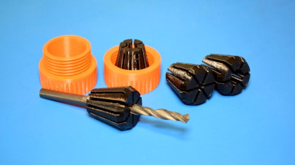
Which is how I found the “Collet Drill Stop” from Adam Harrison. Rather than the traditional ring and setscrew arrangement, his design uses a printable collet that will clamp down on the bit at an arbitrary position without tools. So not only could I avoid a trip to the store by printing this design out, it looked like it would potentially be an upgrade over what I would have bought.
Of course, it’s wise not to take anything for granted when dealing with 3D printing. The only way I could be sure that Adam’s design would work for me was to commit it to plastic and try it out.
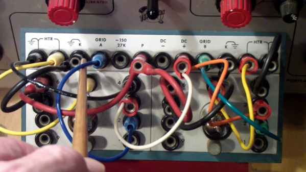
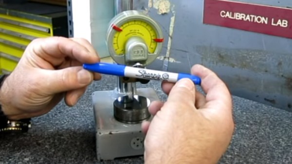
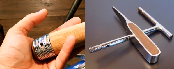
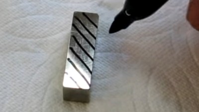 [Tom] from [oxtoolco] got his hands on a tool that measures in 1/10,000,000th (that’s one ten-millionth) increments and was wondering what kind of shenanigans you can do with this Lamborghini of dial indicators. It’s one thing to say you’re going to measure ink, but coming up with the method is the leap. In this case it’s a gauge block — a piece of precision ground metal with precise dimensions and perfectly perpendicular faces. By zeroing the indicator on the block, then adding lines from the Sharpie and measuring again, you can deduce the thickness of the ink markings.