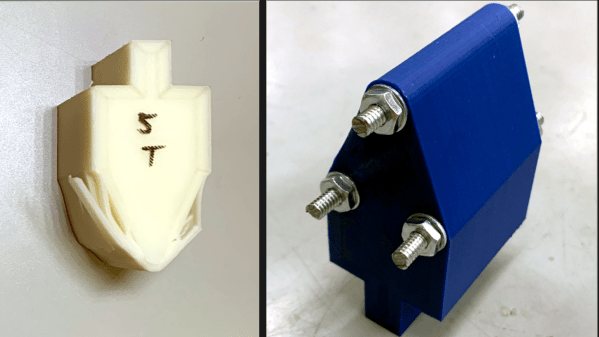
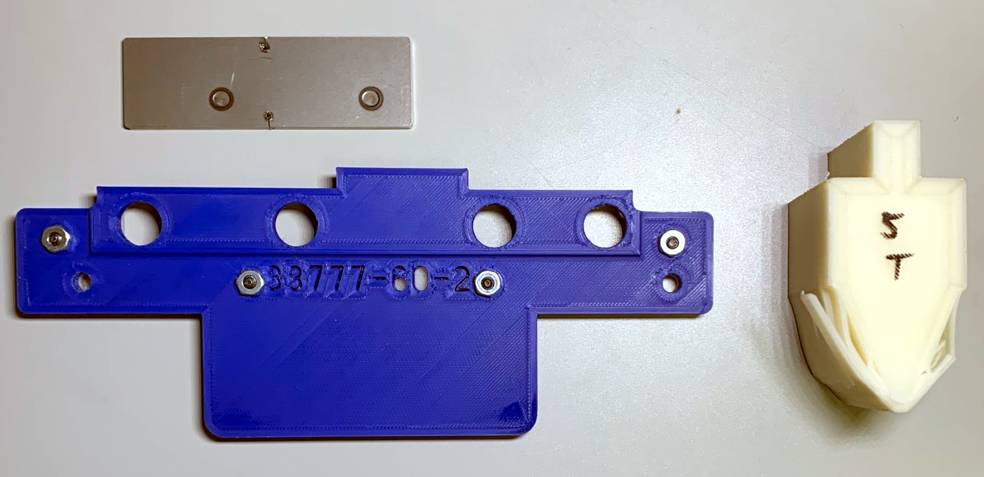
Reddit user [thetelltalehart] has been making brake press tooling with 3D printed PLA, and recently shared an interesting picture of a hybrid brake press punch, shown here on the right, in blue.
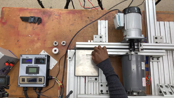
In a press, material such as sheet metal is formed into a shape by forcing the material around the tooling. Some types of tooling can be 3D printed, and it turns out that printed tools are not only fast and economical, but can be surprisingly resilient. You can see such tools in action in our earlier coverage of this approach here and here.
[Thetelltalehart]’s previous work was printed at 80% infill and 12 walls, and failed at 5 tons. The new hybrid tool adds some common hardware that has the effect of reinforcing the tool for very little added expense or complexity. The new tool made it up to 7 tons before failure. It’s a clever idea, and an apparently effective one.
The goal with these 3D printed tools is twofold: doing short-run work, and reducing costly rework when developing “real” tooling. Having to re-cut a tool because it isn’t quite right in some way is expensive and costly, and it’s much easier and cheaper to go through that process with 3D printing instead of metal.