
[Michigan Rocks] says he avoided making rock spheres for a long time on account of the time and cost he imagined was involved. Well, all that is in the past in light of the fabulous results from his self-built Rock Sphere Machine! Turns out that it’s neither costly to make such a machine, nor particularly time-consuming to create the spheres once things are dialed in. The video is a journey of the very first run of the machine, and it’s a great tour.
The basic concept — that of three cordless drills in tension — is adapted from existing designs, but the implementation is all his own. First a rough-cut rock is held between three diamond bits. The drills turn at 100 RPM while a simple water reservoir drips from above. After two hours, there’s a fair bit of slurry and the rock has definitely changed.
[Michigan Rocks] moves on to polishing, which uses the same setup but with progressively-finer grinding pads in place of the cutting bits. This part is also really clever, because the DIY polishing pads are great hacks in and of themselves. They’re made from little more than PVC pipe end caps with hex bolts as shafts. The end caps are filled with epoxy and topped with a slightly concave surface of hook-and-loop fastener. By doing this, he can cut up larger fuzzy-backed polishing pads and stick the pieces to his drill-mounted holders as needed, all the way down to 6000 grit. He shows everything about the pads at the 11:55 mark, and it’s an approach worth keeping in mind.
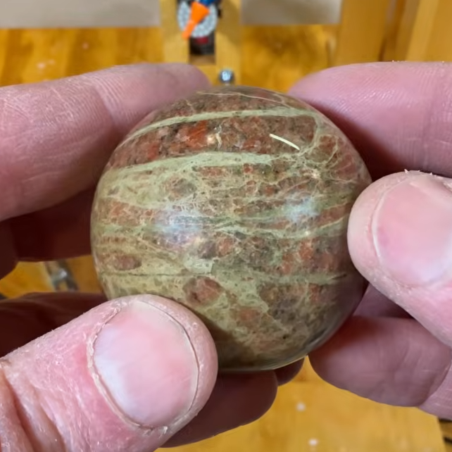
What is the end result like? See for yourself, but we think [Michigan Rocks] sums it up when he says “I wish you could feel this thing, it feels so smooth. It’s so satisfying to roll around in your hands. I’m so happy I made this machine. This is awesome.”
We’ve seen machines for making wooden spheres but this one makes fantastic use of repurposed stuff like inexpensive cordless drills, and the sort of wood structures anyone with access to hand tools can make.
Continue reading “Rock Sphere Machine Produces Off The Charts Satisfaction”


![[nanofix] and his assortment of tweezers](https://hackaday.com/wp-content/uploads/2026/01/nanofix-tweezers-banner.jpg?w=600&h=450)


