They say necessity is the mother of invention. Have you ever been right in the middle of a project, when you realize that you could hack up a simple tool which would make your current task easier? Maybe it’s a coil winder, or a device to hold .100 headers straight in their holes. Faster than you can say “Arabian Nights”, you’re working on a project within a project. It might not be pretty, but it gets the job done. This week’s Hacklet is all about quick tool hacks – little projects that help out around the shop or hackerspace.
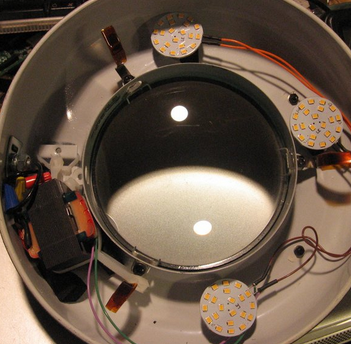 We start with [theonetruestickman] and Magnificent Magnifier LED Coversion. [theonetruestickman] picked up an articulated magnifier lamp at Goodwill for $4. These lamps are a staple of benches everywhere. The only problem was the switch and fluorescent tube were both failing. [theonetruestickman] didn’t feel bad for the lamp though. He pulled out the tube, ballast, and starter, replacing them with LEDs. He used 12 V 3 watt LED modules to replace the tube. Three modules provided plenty of light. An old wall wart donated its transformer to the effort. Since these LED modules are happy running on AC, no bridge rectifier was necessary. The modernized lamp is now happily serving on [theonetruestickman’s] workbench.
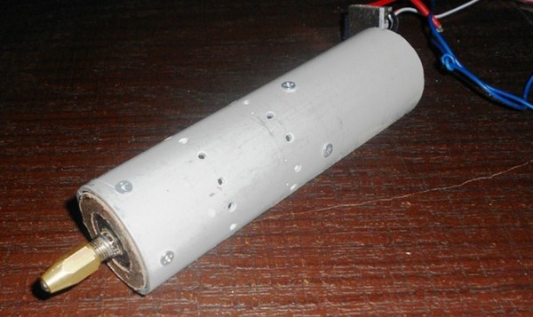
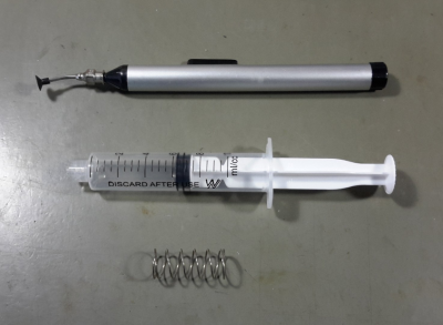 Next up is [Kwisatz] with Pick Up tool hack. [Kwisatz] is a person of few words. This whole project consists of just two words. Specifically, “syringe” and “spring”. Thankfully [Kwisatz] has provided several pictures to show us exactly what they’ve created. If you’ve ever used one of those cheap pickup tools from China, you know [Kwisatz’s] pain. The tiny piece of surgical tube inside the tool creates a feeble vacuum. These tools only hold parts for a few seconds before the vacuum decays enough to drop the part. [Kwisatz] kept the tip of the tool, but replaced the body with a syringe. A spring is used to create just the right amount of vacuum to hold parts on while they are being placed.
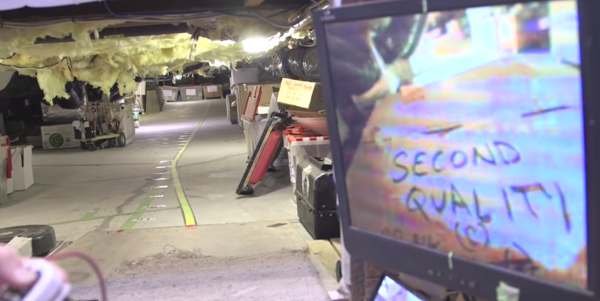
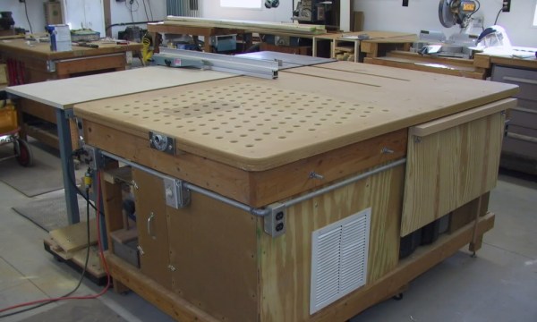
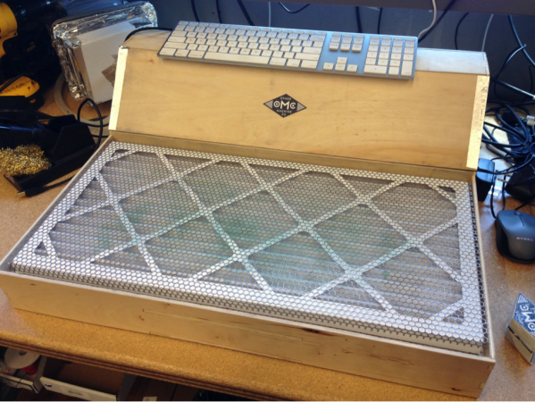
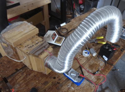 [Dylan Bleier] made his shop air a bit safer to breathe with a simple fume extractor for $20. Solder and flux create some nasty smoke when heated. Generally that smoke wafts directly into the face of the hacker peeking at the 0402 resistor they are trying to solder. A bit of smoke once in a while might not be so bad, but over the years, the effects add up. [Dylan] used two 120V AC bathroom fans, some metal ducting, plywood, and a bit of time to make this fume extractor. [Dylan] is the first to say it’s not UL, CE, or ROHS compliant, but it does get the job done. He even added a screen to keep bugs from flying in from the outdoor exhaust port.
 [ftregan] needed to wind a helical coil for an antenna, so he built Helix Winder. Helices are essentially springs, so that should be easy, right? Turns out that making a nice uniform helix is not the easiest thing in the world. The helix winder is a jig which makes winding these special coils much easier. Holes are drilled at a specific angle in a wooden block. The wire is fed through that block and rolled onto an aluminum tube. Rotating the block on the tube forces the wire into the helix shape. The only downside is that each winder is only good for once dimension of helix.
I’ve noticed that some of these quick hacks don’t get as much love as they deserve over on hackaday.io. So if you notice a cool hack like this, drop a comment and give the project a skull. If you want to see more of these hacks, check out our new quick tool hacks list! See a project I might have missed? Don’t be shy, just drop me a message on Hackaday.io. That’s it for this week’s Hacklet, As always, see you next week. Same hack time, same hack channel, bringing you the best of Hackaday.io!
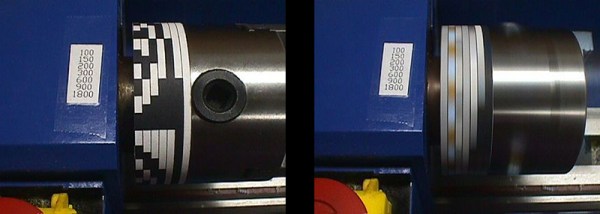

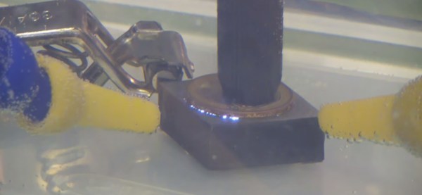
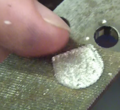 As you can imagine, a single spark won’t erode much metal. EDM machines fire tens of thousands of times per second. The exact frequencies, voltages, and currents are secrets the machine manufacturers keep close to their chests. [SuperUnknown] is zeroing in on 65 volts at 2 amps, running at 35 kHz. He’s made some great progress, gouging into hardened files, removing broken taps from brass, and even eroding the impression of a coin in steel.