When machining metal, it is important to know how fast the cutting tool is traveling in relation to the surface of the part being machined. This amount is called the ‘Surface Speed’. There are Surface Speed standards for cutting different types of materials and it is good practice to stick with those standards in order to end up with a good surface finish as well as maximizing tool life. On a lathe, for example, having a known target Surface Speed in mind as well as a part finish diameter, it is possible to calculate the necessary spindle speed.
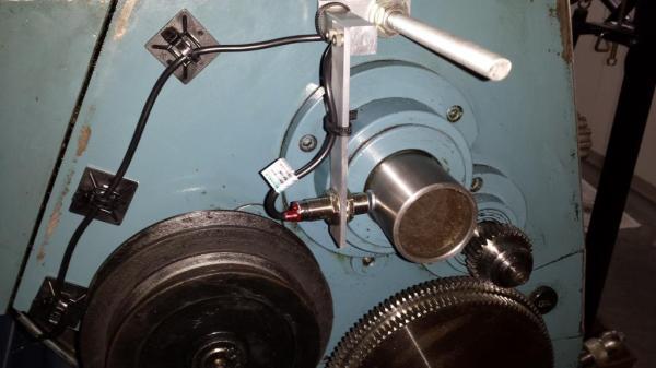
Hobbyist [Paul] wanted a method of measuring his lathe’s spindle speed. Since spindle speed is measured in RPM, it made complete sense to install a tachometer. After browsing eBay for a bit he found one for about $20. His purchase came with the numeric LED display, a mounting bezel and the all important hall effect sensor. The Hall effect sensor measures changes in a magnetic field and in turn varies its output voltage. [Paul] fabbed up an aluminum bracket that supports the sensor just off of the rear of the lathe spindle. A magnet was then glued to the outside diameter of the spindle below the sensor. The once per revolution signal is generated every time the magnet passes the sensor while the lathe is running. The display was mounted to the lathe near eye height by means of another aluminum bracket and case.
After a little work, [Paul] can now keep a close eye on his spindle speed with a quick glance over at his new tachometer display while he’s turning those perfect parts! If this project tickles your fancy, you may want to check out this fantastic DIY tachometer or this one that uses a soundcard.
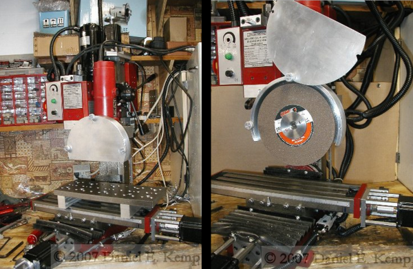
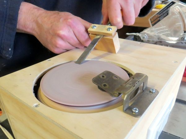
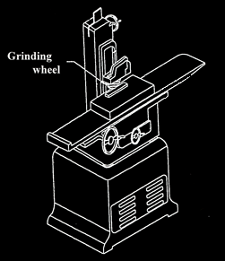 [Daniel] is a tool guy and wanted a Surface Grinder. He didn’t need a super-accurate commercial grinder so he decided to