Component Storage Roundup

It’s been suggested that the first self-replicating computer virus was a single IC that eventually expanded into multiple plastic component storage boxes. Organizing components by their values is a huge PITA as well. Here’s some solutions we’ve found:

Photo Boxes

[Mathew] sent in his organization scheme that uses 4×6 photo boxes. Better get those boxes while they’re hot – we can’t remember the last time we used film.

Use a binder

This instructables uses binders for storage. Good for passives, but unless someone can find anti-static bags for a binder, we’ll keep our ICs separate.

The only way to organize resistors

[Johannes] stores his resistors on a sheet of styrofoam. The grid has the first color band on the left side and the second color band on the top. Extremely, extremely clever. We’re wondering why we Radio Shack didn’t come up with this in the 70s. The grid could be laid out on a log scale, though.

If Susan is lazy, why does she do all the work?

[D.C. Boyce] hacked up a couple of lazy susans, built frames out of 2x4s and mounted plastic component drawers on them. The result is probably more space than we’ll ever need. To keep things simple, he wrote a database program to keep track of everything.

Adding USB Connectivity To Old Benchtop Tools

frequency_counter_hacked_for_usb_connectivity

[Scott] was recently given a frequency counter, and once he brought it home, he started contemplating how he could possibly make it better. While the counter worked well as-is, he wanted to find a way to record data readings over a reasonably long period of time. He figured that interfacing it with his computer would be the best way to do this, but he had to find a way to connect the devices first.

He started poking around inside the frequency counter and stumbled upon a possible data source when taking a closer look at the display board. He found that he could read the frequency data as it was being written to the display, and send that data to his computer. He used an ATMega48 to intercept the data and code from the V-USB project to bit-bang the data to his PC over USB.

Now, anything he sees on the frequency counter can be easily collected and graphed on his computer with little fuss.

Stick around to see a quick video demonstration of his hack in action.

Continue reading “Adding USB Connectivity To Old Benchtop Tools”

Arduino Powered 2.4 GHz Spectrum Analyzer

[Fred] dropped a note in our tip line to let us know about arduino forum user [bilbo]’s latest project: A 3-in-one spectrum analyzer, oscilloscope, volt-meter combo. The build consists of an Arduino, radio board and Nokia 5110 LCD breakout board.  The (thin) video after the jump shows the rig in action. Though soldered to a full sized perf-board we can see later, smaller, battery powered versions prove useful in rooting out wayward bluetooth signals, or just finding that lost microwave oven. Although [bilbo] uses the same radio board as similar builds  his creation boasts several different display modes, as well as doubling as a volt meter and miniature-oscilloscope. There is no shortage of previous spectrum analyzer builds, but this one is the first one we have seen running on an Arduino.

Thanks for the tip [Fred]! If you feel like wedging some frequency scanning capabilities into your next project don’t forget to check out [bilbo]’s forum posts for source code!

Continue reading “Arduino Powered 2.4 GHz Spectrum Analyzer”

Resistor Substitution Box

[Vincent] on the EEVblog forums had an idea for an inexpensive resistor substitution decade box.

The build uses cheap decimal thumbwheel switches he bought on eBay. Each switch is wired up with resistors for each digit, and each switch is wired up in series. The result is a small, easy to read resistor box with a range of 1 Ω to 10 MΩ.

Continue reading “Resistor Substitution Box”

DIY Robot Remote Control

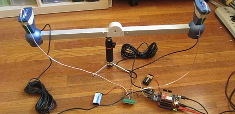
[Patrick] wanted a remote control to control some of the robots he’s built. He also wanted to get some data back from his robots, so an inexpensive off-the-shelf solution wouldn’t be up to the task. Like all good geeks, [Patrick] decided to build what he needed.

For analog control, [Patrick] decided to use a Wiimote nunchuck. This turned out to be a very good choice – the nunchuck has a 2-axis joystick and 3-axis accelerometer in one small, easy to interface package . The wireless radio is taken care of with an XBee module. For the microcontroller, custom “lcd backpack” was created that provides an I2C port for the nunchuck, inputs for the buttons and the single pot, and 2 serial ports for the FTDI and XBee.

Continue reading “DIY Robot Remote Control”

Cheap And Easy PCB Agitator From An Old CD-ROM

cdrom_pcb_agitator

Instructables user [mzsolt] enjoyed making his own PCBs, but he wanted to speed up the etching process just a bit. While some people put together elaborate bubble tanks and agitators, he wanted to keep his simple and more importantly, cheap.

He looked around the house and discovered an ancient CD-ROM drive that was collecting dust, which he figured would make a great agitator for smaller projects. He picked up a decade counter and a handful of other cheap components, then got busy pulling the drive apart. He connected the motor and the drive’s limit switches to the decade counter, which controls the entire setup.

When powered on, the drive ejects, taking his container full of etchant with it. When the drive hits the outer limit switch, the decade counter reverses the motor until it hits the inner switch, reversing the motor once again.

As you can see in the video below, it works reasonably well. He suggests using a variable power supply to regulate the motor’s speed, but a variable pot would probably work just as well. Obviously the agitator is best suited for smaller projects, but since it was so cheap to put together, you won’t hear us complaining.

Continue reading “Cheap And Easy PCB Agitator From An Old CD-ROM”

Accounting For Material Loss When Laser Cutting


When you cut something out, you lose a bit of material in the process. Think of a table saw and the sawdust it produces, that’s the waste material lost in an area the width of the blade. It’s really easy to measure that, just measure the blade. But [James] started wondering about a good way to measure material loss from a laser cutter.

Why does it matter? If you’ve designed pieces that should fit together with each other, loss of material can lead to joints that aren’t tight. [James] figured out that the loss could be measured by making several cuts within a rectangular frame. You can see his test pieces above, with ten strips cut out of each frame. After the laser is done doing it’s work just slide all the pieces together and measure the opening created at one end. It helps to have an enhanced caliper to make the measurement easy to read. Now divide that distance by the number of laser passes and account for that dimension next time you design parts for the cutter.