Turn A Logic Analyzer Into A Signal Generator Using Only Software

One thing we learned by watching [Alton Brown] on all of those Good Eats episodes is that a multitasker is way better than a unitasker. [Joost] is thinking along the same lines by taking a fantastic tool and adding a useful function to it. His software project turns a USB Saleae Logic Analyzer into a signal generator.

There are already a multitude of reasons to own one of these fantastic tools. But the ability to use it to generate up to 8 channels of PWM signals is a welcome addition. It is capable of producing frequencies from 1Hz up to 1MHz at a sample rate of 4 MHz. It uses the original SDK and doesn’t require any changes to the hardware (we would’ve thought new firmware was necessary, but happily that’s not the case). The one caveat is that right now this only works with Windows machines running the .NET version 3.5 or higher. It looks like an MSI installer package is all that’s available for download so the thoughts of easily porting this to other operating systems have been dashed unless [Joost] decides to share his source code.

Edit 7/12/2016: [Joost]’s webpage is down, but he moved it to Github.

Serial Port JTAG Programmer

If you’re planning to do some hacking with CPLD or FPGA chips you’ll need a way to program them. JTAG is one of the options and here’s a cheap method that uses the serial port (translated).

This method requires only four signals (TDI, TMS, TCK and TDO) plus ground. But the problem is that an RS232 serial port operates with 12V logic levels and the JTAG side of the programmer needs to operate with the logic levels native to the device you’re programming. Commercial programmers use a level convert IC to take care of this for you, but that doesn’t mesh with the cheap goal of this project. Instead, [Nicholas] uses Zener diodes and voltage dividers to make the conversion. There is also an LED for each data signal to give some feedback if you’re having trouble.

You can use this along with a programming application that [Nicholas] whipped up using Visual Studio. It works well via the serial port, but he did try programming with a USB-to-Serial dongle. He found that this method slows the process down to an unbearable 5-minutes. Take a look, maybe you can help to get that sloth-like programming up to a manageable speed.

[Thanks Alex]

PCB Milling With A Makerbot

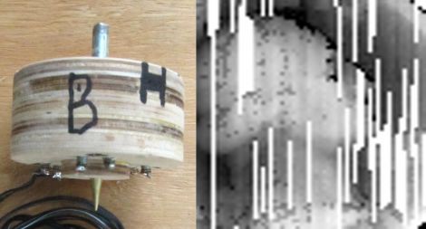
[Keith] wanted to use his makerbot for some PCB milling, but he ran into a pretty big problem. The platform that his PCB would sit on was mounted with a layer of double sided foam tape and was not perfectly aligned to the head. Not only that, but it would tilt when pressure was applied. This made the result of the milling completely unacceptable. To remedy this, he made a new platform that is not only rigid, but he has made it so that there is the ability to adjust it for perfect alignment via adjustment screws in the 4 corners. At the beginning of each session, he can be absolutely sure that everything is aligned perfectly and his PCBs show a huge improvement. You can see a comparison of the two in the following picture.

[via HackedGadgets]

Arduino I2C Sniffer

[Johngineer] found himself in need of an I2C sniffer, but didn’t have one available. Necessity is the mother of invention, so he put together this I2C sniffer sketch for Arduino. The arduino will record what is going on for a set time interval, then dump the data via serial as a .csv. You then have to plot it to see what is going on. [Johngineer] recommends Livegraph, since it is portable and easy. As you can see in the code, the time interval is adjustable, but you have the physical limitations of the RAM on the board to consider. This seems like a pretty handy piece of code stored around, effectively giving you a passable I2C sniffer in a pinch.

DIY Spectrophotometer

[Charlie] has been making a DIY Spectrophotometer, and while it is a “shambling mess of information-age technology!” it is still much better than ours. Focused around an arduino, bits of lego, and a flashlight, this creative device rotates a diffraction grating (flake of compact disc) aimed at a photo resistor. As the light spectrum is passed over the sample, the photo resistor measures how much light is reflected and that data is passed back to a pc.

As nothing is as ever easy as it should be, a big problem popped up with using a servo. It was way too course, meaning the entire spectrum would be jumped over in 6 steps. A quick robbery of a gear assembly from a floppy disk drive and the motor movement was smoothed out. A little too well because 120 degrees of the servo is not quite enough to cover the entire spectrum. Oh well there is always room for improvement.

1Hz Timebase

Check out this nice simple method of achieving a 1Hz timebase. This is basically a lesson in dividing crystal frequencies in circuits to get the desired result. In this case, they are starting with a 32.768KHz crystal and dividing it down. Instead of using an NE555 like many projects, he chose to go a direction that would yield results less prone to drifting with temperature variation. The method chosen was a CD4060 frequency divider, basically just a chain of flipflops. The divider is one step short of getting to the desired result so an additional flipflop has to be added. This is pretty basic stuff, but a great read. They go into detail as to how it all works and why you would use this method.

Pssst, hey, remember that time I told you to just use a 1Hz crystal? yeah, we can laugh at that again.

[via HackedGadgets]

Open Source Linear Bearing System

makerslide

While we normally don’t make it a habit to feature Kickstarter projects, we couldn’t pass this one up. [Barton Dring] from BuildLog.net is putting together a project called MakerSlide that we’re sure will interest many of you out there.

Through his various CNC builds, he has found that one of the more expensive and frustrating components to obtain is a linear bearing system. He notes that commercial systems are expensive, and while an occasional eBay bargain can be found, it’s not the ideal way of going about things. He also points out that homebrew systems usually work after some tuning and adjustments, but can be time consuming to build.

He is proposing a v-groove bearing system, complete with wheels made from Delrin, as a standardized replacement for all of the aforementioned solutions. He anticipates selling the rails for about 10 cents per centimeter, putting the average cost of a 4 foot system around $20.

As a bonus, he is offering up free MakerSlide materials to anyone that sends him a “new, innovative  or interesting open source design or basic idea that uses the material.” You would only have to pay shipping in order to get your new project off the ground.

Standardization is always good, and seeing this rail system go into production would definitely benefit the hacker community. Take a minute to check it out if you are so inclined.