Open Source Laser Cutter (v2)

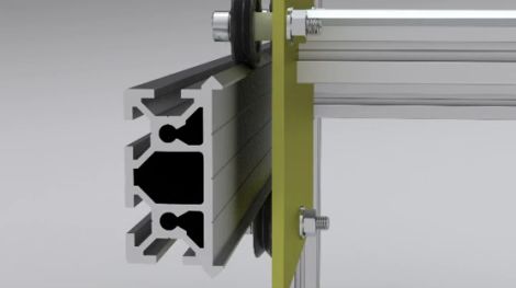
The Buildlog.net 2.x Laser is a second generation open source laser cutter that definitely improves the design of the first model. The 2 axis machine (optional vertical axis is manual or an upgrade is available) boasts a large 12” x 20” x 4” workspace while being smaller than its predecessor, fitting a table top design.

The older model had a goal of being self replicating, which limited the types of materials used, the new 2.x model drops that goal and uses stronger metal parts. Electronics are now modularized that allow easier and cleaner wiring, though you will still need a controller board.

There is an XMOS based controller provided on the main page of BuildLog.net, along with mechanical drawings, schematics, gerbers, instructions for both machines, and kit parts (for the first model) along with resources for the heavy items like laser tubes and power supplies.

Super Winch Makes Sledding 100% More Fun

sledding_winch

As every kid quickly finds out, sledding in the winter is awesome until you have to trudge back up to the top of the hill. If your sledding run is reasonably short, this isn’t a problem, but if you sled on huge hills like [Josh], you need to figure something out.

He had a go kart motor sitting around, so he figured he might as well put it to good use as a sledding winch. The winch runs a continual loop of over 1000 feet of rope, and is able to pull 3 adults up a 30 degree incline fairly easily. They say that necessity is the mother of innovation, but at some point you have to ask, “Does sledding really require an 8 HP motor and a continuously variable transmission?” The answer, of course is a resounding “Yes!”

Not only does this winch allow [Josh] and his friends to get back to real business of sledding in a hurry, it actually makes sledding fun in both directions.

Keep reading to see a video of the winch in action, and be sure to check out some other fun uses for winches we have featured in the past.

[via Neatorama]

Continue reading “Super Winch Makes Sledding 100% More Fun”

Easy To Build Rig Prevents Reflow Soldering Mishaps

reflow_soldering_rig

[Erich aka VK5HSE] performs quite a bit of solder reflow work, but has always been concerned about bumping his circuit boards once the solder has liquified and is ready to be removed from the heat source. He says that removing workpieces from toaster ovens often results in the unintentional jarring of a circuit board full of components sitting on molten solder, and he wanted to find a solution.

Using some off-the shelf components from a local hardware store, he built a rig that fits on top of a hot plate, allowing him to move hot circuit boards away from the heat source in a smooth controlled motion. The rig is pretty simple, not only preventing unwanted workpiece movement, but also making it easy to regulate the amount of time a circuit board is allowed to heat.

He suggests that his design is not absolutely ideal, and that it can easily be improved upon in several ways without adding significant cost to the project.

555 Inductance Meter

[Apexys] is performing some experiments with switched-mode power supplies and needed to compare the inductance of the coils he was using. His multimeter doesn’t have an inductance testing function, but he does have a 555 timer on hand. He put the 555 and some other parts together to create his own L meter. The writeup includes the theory behind this meter, with an incoming AC source converted to a voltage by an RC network.

Once he’d worked out the design it was time to build the circuit. Instead of printing a circuit board he created what he calls a DCB; Drawn Circuit Board. We’ve got to admit that this was way faster than using toner transfer or soldering point-to-point. We also like his use of an Erlenmeyer flask and a torch to heat the etchant. We don’t make PCBs in the winter because our Cupric Chloride is too cold to use outside but that may change now. The final piece in the puzzle is an analog meter which he pulled from an extra microamp meter he had on hand. Check out the demo after the break.

Continue reading “555 Inductance Meter”

Magnetic SMD Pick And Place

magnetic_pick_and_place

[svofski] sent us this pick and place robot (Google translation) that he found , and it’s quite unique. The majority of the components that make up this pick and place have been recycled from old computer equipment. The X-axis motion is accomplished using old printer parts, while an old CD-ROM drive was gutted to provide motion along the Y-axis. Floppy drive components were ultimately chosen to give the pick and place Z-axis motility.

What makes this pick and place unique however is the way in which components are moved. Most pick and place devices we have seen rely on suction in order to lift and carry components, but this one uses a magnet instead. The machine is used to build small circuit boards for a robotics platform offered on the builder’s web site, which primarily utilizes SMD parts. Once they realized that the majority of their small components were ferromagnetic, they built a hand-wound electromagnet to lift them. While the design limits the usage of the device to strictly ferromagnetic parts, they have a very specific need, which this fills perfectly.

Another unique aspect of this pick and place is the grooved table that sits under the workpiece. It is used to route up to four reels of SMD components, with the placement head providing all of the reel motion instead of relying on separate motors.

If you have a few minutes, be sure to check out the video of the pick and place at work.

Easy DIY Stroboscope

stroboscope_output

Looking for something to do in his downtime, [Mista Sparkle] decided that building a simple stroboscope was in order. He already had a set of six LEDs connected to his Arduino from a previous project, so he added a potentiometer to control the rate at which the LEDs flashed, and dug into the IDE.

During his build he discovered that using the Arduino millis() function at high speeds provides terrible resolution, while using the micros() function exclusively limits his low end measuring capabilities. He desired a better range of measurement, so his program was broken into main functions: One which measures the LED flashing frequency in milliseconds and another that measures the LED flashing frequency in microseconds. This allowed him to gauge rotational frequencies from 577 to 30,000 RPM.

[Mista Sparkle] admits that he is not yet well-versed in driving displays with the Arduino, so he views his readings over a serial connection on his PC. Hopefully we’ll see an updated version with those features in the near future.

Propeller Platform Logic Analzyer

[Wulfden’s] new gadget is a 28 channel 3.3 volt digital logic analyzer. Powered by a Parallax Propeller running at 100MHz (permitting a 10 nanosecond sampling rate), using all though hole parts, and open design so it is possible to whip up your own.

Data is collected and sent to a host computer running Propalyzer which looks to be a very nice logic analyzer front end, and sports all the needed features and a HP inspired design. The design of the board allows you to plug it on to any Propeller Platform board, and this is very handy for those who have other Propeller boards, though others will have to source a regulated 3.3 volt power supply, and serial converter.

Overall this looks to be a very handy tool to have around, whether you opt for the kit to use on your Propeller Platform boards or roll your own, the features and cost are very attractive if you need a logic analyzer.

Join us after the break for a quick introduction video by [Nick] (of Gadget Gangster)

Continue reading “Propeller Platform Logic Analzyer”