GPS-based location services will be around with us forever. If you’re in the outback, in the middle of the ocean, or even just in a neighborhood that doesn’t have good cell coverage, there’s no better way to figure out where you are than GPS. Using satellites orbiting thousands of miles above the Earth as a location service is an idea that breaks down at some very inopportune times. If you’re in a parking garage, you’re not using GPS to find your car. If you’re in a shopping mall, the best way to find your way to a store is still a map. Anyone every tried to use GPS and Google Maps in the hotel/casino labyrinth that is the Las Vegas strip?
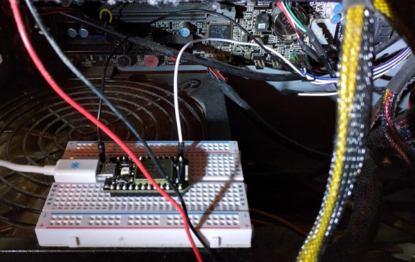
[Blecky]’s entry for the Best Product competition of the Hackaday Prize aims to solve this problem. It’s an indoor location service using only cheap WiFi modules called SubPos. With just a few ESP8266 modules, [Blecky] can set up a WiFi positioning system, accurate to half a meter, that can be used wherever GPS isn’t.
The idea for a GPS-less positioning system came to [Blecky] after a caving expedition and finding navigation though subterranean structures was difficult without the aid of cell coverage and GPS. This got [Blecky] thinking what would be required to build a positioning service in a subterranian environment.
The answer to this question came in the form of a cheap WiFi module. Each of the SubPos nodes are encoded with the GPS coordinates of where they’re placed. By transmitting this location through the WiFi Beacon Frame, along with the transmitted power, any cell phone can use three or more nodes to determine its true location, down to a few centimeters. All of this is done without connecting to a specific WiFi network; it’s a complete hack of the WiFi standard to allow positioning data.
The most shallow comparison to an existing geolocation system would be a WiFi positioning system (WPS), but there are several key differences. In WPS, the WiFi APs don’t transmit their own location; the AP is simply cross-referenced with GPS coordinates in a database. Secondly, APs do not transmit their own transmit power – important if you’re using RSSI to determine how far you are from an Access Point.
The best comparison to an indoor location service comes from a new Decawave module that sets up ‘base stations’ and figures out a sensor’s location based on time of flight. This, however, requires additional radios for each device receiving location data. SubPos only requires WiFi, and you don’t even need to connect to an AP to get this location data; everything is broadcast as a beacon frame, and every device with WiFi detects a SubPos node automatically.
As an entry to the Hackaday Prize Best Product competition, there is an inevitable consideration as to how this product will be marketed. The applications for businesses are obvious; shopping malls could easily build a smartphone app showing a user exactly where in the mall they are, and provide directions to The Gap or one of the dozens of GameStops in the building. Because the SubPos nodes also work in 3D space, parking garage owners could set up a dozen or so SubPos nodes to direct you to your exact parking spot. Disney, I’m sure, would pay through the nose to get this technology in their parks.
Already [Blecky] is in talks with one company that would like to license his technology, but he’s not focused only on the high-dollar business accounts. He already has a product that needs manufacturing, and if he wins the Best Product competition, he will be working on something for the hacker/homebrew market. The price point [Blecky] sees is around $15 a node. The economics of this work with the ESP WiFi module, but [Blecky] is also looking at alternative chip sets that would allow for more than just RSSI position finding; an improved version of the SubPos node not based on the ESP-8266 could bring time of flight into the mix, providing better position accuracy while still being cheaper to manufacture than the current ESP-based solution.
[Blecky] has a great project on his hands here, and something we will, undoubtedly, see more of in the future. The idea of using WiFi beacon frames to transmit location data, and received signal strength to suss out a position is groundbreaking and applicable to everything from spelunking to finding your car in a parking garage. Since the SubPos system isn’t tied to any specific hardware, this could even be implemented in commercial routers, giving any device with WiFi true location data, inside or out. It’s also one of the top ten finalists for the Hackaday Prize Best Product competition, and like the others, it’s the cream of the crop.
Continue reading “Hackaday Prize Best Product: WiFi Location Services”