Resistance Is Futile, You Want This LED Cube

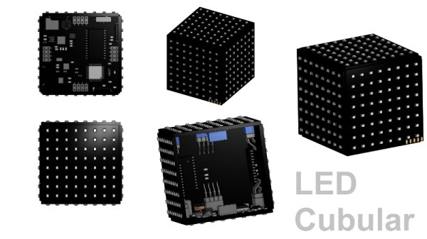
We’re suckers for a good desk toy here at Hackaday, so this 2019 Hackaday Prize entry from [Jack Flynn] certainly caught our eye. The idea is that by using professionally manufactured dual layer PCBs and only surface mount components, you can create a cube that has an LED matrix on each face and all of the electronics hidden within. We’re not entirely sure if there’s any practical application for such a device, but we know we’d certainly like to have one blinking madly away on our shelf regardless.

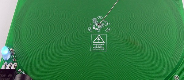
Before having any of the PCBs manufactured, [Jack] is putting a considerable amount of thought into the design so he doesn’t end up painting himself info a corner (which is of course eight times as bad when you’re building a cube). By importing the PCB files into OnShape, he’s able to “assemble” a virtual representation of the final product to better understand how everything will fit together. He wants to limit the amount of times the cube will need to be pulled apart, so everything from how it will sit in its 3D printed cradle to the placement of breakaway tabs that ensure the internal power switch is accessible are being carefully planned out.

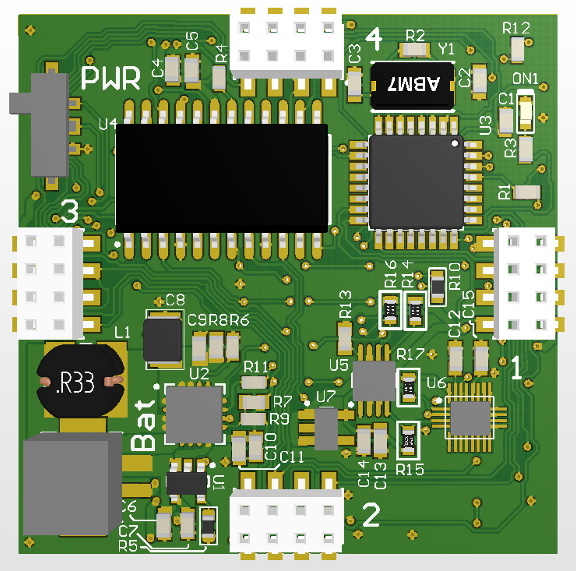
The current design puts the “brains” on the bottom board, with every other panel holding a daisy-chained MAX7219 to drive its own individual 64 LED matrix. Initially the dimensions of the ATmega328p powered cube will be 42 x 42 x 42 mm, with a total of 384 LEDs. Ultimately, [Jack] hopes the modular nature of the design could allow the size of the cube to be increased, or perhaps even take on a different shape entirely.

Generally the LED cubes we see are of the more wiry variety, so it’s particularly interesting when they take on solid forms like this one. Given the nearly universal popularity of blinking LED gadgets, we think this particular project is well positioned to make the leap from one-off hack to a commercial product.

Continue reading “Resistance Is Futile, You Want This LED Cube”

GPS Self-Adjusting Clock With An E-Ink Display

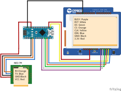
If you mention a clock that receives its time via radio, most people will think of one taking a long wave signal from a station such as WWVB, MSF, or DCF77. A more recent trend however has been for clocks that set themselves from orbiting navigation satellites, and an example comes to us from [KK99].  It’s a relatively simple hardware build in that it is simply an Arduino Nano, GPS module, and e-ink display module wired together, but it provides an interesting exercise in running through the code required for a GPS clock.

It does however give us a chance to remember the story from last year surrounding WWVB, as a budget proposal last year mooted the prospect of the closure of the Fort-Collins-based time signal transmitter. Were that to happen an estimated 50 million American clocks would lose their reference, and while their owners could always update them manually, there will always be time-based systems to which that won’t be applied for whatever reason.  Europeans meanwhile are safe in their time transmissions for now , but in case they think they have their mains grid to fall back on it’s worth remembering the time they lost six seconds.

GPS satellite image: USAF [Public domain].

The Simplest Of Pseudo Random Number Generators

A truly random number is something that is surprisingly difficult to generate. A typical approach is to generate the required element of chance from a natural and unpredictable source, such as radioactive decay or thermal noise. By contrast it is extremely easy to generate numbers that look random but in fact follow a predictable sequence. A shift register with feedback through an XOR of its output and one of its stages will produce a continuous stream of pseudo-random bits that repeat after a set period.

[KK99] has created the simplest possible pseudo-random binary sequence generator, using a three-bit shift register. It’s realised on a pleasingly retro piece of perfboard, with a CD4047 as clock generator and a 74HC164 shift register doing the work. Unusually the XOR gate is made from discrete transistors, 2N3053s in bulky TO39 packages, and for a particularly old-fashioned look a vintage HP LED display shows the currently generated number. A relatively useless pseudo-random sequence with a period of seven bits is the result, but the point of this circuit is to educate rather than its utility. You can see it in operation in the video below the break.

We had a demonstration of the dangers of using a pseudo-random sequence back in 2016. The German military cipher nicknamed “Tunny” by British codebreakers relied upon a mechanical sequence generator, and the tale of its being cracked led to the development of Colossus, the first stored-program electronic computer.

Continue reading “The Simplest Of Pseudo Random Number Generators”

Power Stacker, A Modular Battery Bank

Many of us will own a lithium-ion power pack or two, usually a brick containing a few 18650 cylindrical cells and a 5 V converter for USB charging a cellphone. They’re an extremely useful item to have in your carry-around, for a bit of extra battery life when your day’s Hackaday reading has provided a worthy use for most of your charge. These pack are though by their very nature inflexible, no matter how many cells you own, the pack will only ever contain the number with which it was shipped. Worse, when those cells are discharged or even  reach the end of their lives, they can’t be swapped for fresh ones. [Isaacporras] has a solution for these problems which he calls the Power Stacker, a modular battery pack system.

At its heart is the Maxim MAX8903 lithium-ion charge controller chip, of which one is provided for each cell. A single cell and MAX8903 with a DC to DC converter for 5 V output makes for the simplest configuration, and he has a backplane allowing multiple boards to be connected and sharing the same charge and output buses.

An infinitely configurable battery bank sounds great. It’s looking for crowdfunding backing, and for that it has an explanatory video which you can see below. Meanwhile if you’d  like to try for yourself you can find the necessary files on the hackaday.io page linked above.

Continue reading “Power Stacker, A Modular Battery Bank”

A USB -C Soldering Iron For Weller Tips

There was a time when a decent temperature controlled soldering iron took the form of the iron itself and a box of electronics, but now it’s just as likely to be a miniaturised affair with the temperature controller built into a slim and lightweight handle. Irons such as the Miniware TS series have become firm favourites, displacing a traditional soldering station for many.

[Thomas.lepi] has combined the best of both worlds, with a TS-style microprocessor-driven handle driving the familiar Weller RT elements. Its interface is very simple, but through its USB power socket a serial port provides opportunities for adjustment. Providing control is an STM32F042G6U6 ARM Cortex M0 microcontroller, with USB power control coming from an STUSB4500QTR .

If you are used to irons such as the Miniware TS100 then this one with its smartly 3D-printed case will be very straightforward to use. Whether or not the ready availability of the TS100 or its USB-C sibling would remove the need to build this iron is up to you, but then again that’s hardly the point. The Weller tips are some of the better ones of their type, so perhaps that might make this project worth a second look.

Continue reading “A USB -C Soldering Iron For Weller Tips”

Here’s A Tesla Coil You Can Wear

It’s badgelife season, and if you need an idea for a killer piece of wearable electronics, look no further than this PCB Tesla coil. Yes, it’s killer, doubly so if you’re wearing a pacemaker.

This project was inspired by an earlier Tesla coil on a PCB project that used 160 turns of 6 mil traces on a circuit board as the secondary. All the electronics are there, and it’s powered by USB. Plug this thing in, and you have a pocket full of lightning that’s approximately 30kV. It probably won’t kill you if you touch it, but let’s not test that too much. [Bobricious] took this idea and ran with it, stripping the circuit down to its bare minimum. Now it’s just a single transistor, with all the other parts printed on a circuit board.

There is one problem with making a Tesla Coil on a PCB, and that’s the number of turns on the coil. Any Tesla coil you’ll find is really just the clever application of a single thin wire wrapped around itself a few hundred or thousands of times. This Tesla coil is no different, and in this case it’s 240 turns of a single trace wrapping around a PCB that is 150mm square. [Bobricius] is one of the kings of putting tiny coils on a PCB, and his fiberglass brushless motor is a testament to that. We also just covered his circular linear motor raceway which also uses PCB coils.

The circuit is simple, just a power jack that accepts something around 20 Volts, a single BD243 transistor, an LED, and an 82k resistor. With that, you can lay a small neon tube on the PCB and watch it light up. With another PCB and another neon tube, this circuit board can transfer wireless power. It’s a fun toy, and it’s all PCB tech.

The Pocket Emulator That Will Fit In Your Pocket

If there’s one thing tiny Linux Systems on a Chip are good for, it’s emulation. There’s nothing like pulling out an emulation console on the bus for a quick game of old-school NES Tetris, or beating the next level in Super Mario World. This is the smallest emulation console ever. It’ll fit in your pocket, and it has a bright, vibrant screen. It doesn’t get better than this.

This project is an improvement on two projects, both of which are some of the top projects on hackaday.io, the best place on the Internet for hacks and builds. The Keymu is (or was, at the time) the smallest emulation console ever, built as a miniaturized version of the Game Boy Advance SP in a 3D printed case and powered by the Intel Edison. The Edison doesn’t exist anymore, so after that development moved over to the Funkey Zero, a tiny console built around the AllWinner V3s chip and a 240×240 display. Both of these are tiny, tiny consoles, but as silicon gets better there’s always better options, so it’s back to the drawing board.

The design of the Funkey Project is again built on the AllWinner V3S SoC with 64MB of DDR2 DRAM. There’s a 1.5″ display with 240×240 resolution, and of course this retro emulation console retains the classic and very useful clamshell form factor of the famous Game Boy Advance SP.

Already, this project is in the works and it’s shaping up to be one of the most popular projects on hackaday.io ever. Everyone wants an emulation console, and this is the smallest and tiniest one yet. Whether or not this project can carry through to production is another matter entirely, but we’re eager to find out.