Racing The Beam On An ATtiny

For the last thirty or so years, the demoscene community has been stretching what is possible on computer systems with carefully crafted assembly and weird graphical tricks. What’s more impressive is hand-crafted assembly code pushing the boundaries of what is possible using a microcontroller. Especially small microcontrollers. In what is probably the most impressive demo we’ve seen use this particular chip, [AtomicZombie] is bouncing boing balls on an ATtiny85. It’s an impressive bit of assembly work, and the video is some of the most impressive stuff we’ve ever seen on a microcontroller this small.

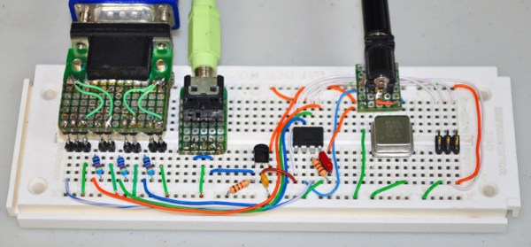
First, the hardware. This is just about the simplest circuit you can build with an ATtiny85. There’s an ISP header, a VGA port with a few resistors, a 1/8″ audio jack driven by a transistor, and most importantly, a 40MHz crystal. Yes, this ATtiny is running far faster than the official spec allows, but it works.

The firmware for this build is entirely assembly, but surprisingly not that much assembly. It’s even less if you exclude the hundred or so lines of definitions for the Boing balls.

The resulting code spits out VGA at 204×240 resolution and sixty frames per second. These are eight color sprites, with Alpha, and there’s four-channel sound. This is, as far as we’re aware, the limit of what an ATtiny can do, and an excellent example of what you can do if you buckle down and write some really tight assembly.

Continue reading “Racing The Beam On An ATtiny”

Comic Boxes Reflect Owner’s Skills

We are the culmination of our experiences. We build with the tools we’re familiar. We design with the decorations we like. Sometimes this thinking leads to a project that looks like a kindergartener who has dressed in a pink tutu and a camo shirt. Sometimes our experience leads us to make something functional and elegant. [jordanlund] combined his work experience in a library, 3D modeling skills, and love of comic books to turn a hodgepodge pile of scribbled-upon boxes into an orderly collection of comic books in boxes adorned with brass drawer pulls.

3D printing bridged the gap between the brass card catalog drawer pulls he knew well from the library and the crates of comics he kept at home. Custom brackets allowed the drawer pulls, which were meant to be screwed into wooden drawer faces, to work with cardboard boxes. The drawer pulls have a slot for labels so there will be no need to rip off sticky labels later or scrawl with a permanent marker. Perhaps [jordanlund] is merely a bibliophile with a 3D printer but if we didn’t know better, we might think those boxes were meant to have the drawer pulls installed.

Engage your own love of literature with this wordplay riddled appeal for libraries. or make your home library a little more fantasical with a secret door.

A Relay Calculator With DIY Neon Displays, Just Because

This looks like one of those projects that started out as a glimmer of an idea and led down a rabbit hole. But it’s a pretty cool rabbit hole that leads to homebrew neon seven-segment displays on a calculator with relay logic.

It’s a little thin on documentation so far, but that’s because [Mark Miller]’s build is one of those just-for-the-fun-of-it things. He started with a bag full of NE-2 tubes and the realization that a 3D-printed frame would let him create his own seven-segment displays. The frames have a slot for each segment, with a lamp and current limiting resistor tucked behind it; with leads brought out to pins and some epoxy potting, these displays would be hard to tell from a large LED seven-segment. Rolling your own displays has the benefit of being able to extend the character set, which [Mark] did with plus-minus and equal sign modules. All of these went together into a two-banger calculator — addition and subtraction only so far — executed in relays and vacuum tubes. Version 2.0 of the calculator regressed to all-relay logic, which must sound great.

We heartily regret the lack of a satisfyingly clicky video, but we’ll give it a pass since this is so cool. We’ll be watching for more on this project, but in the meantime, if you still need to get your click on, this electromechanical BCD counter should help.

Autodesk Introduces Parametric Part Generation

The hardest part of any PCB design is adding parts and components. You shouldn’t use random part libraries, and creating your own part libraries is just a pain. Why have we endured this pain for so long, especially considering that most components follow a standard? Add in the fact that 3D modeling and rendering a board in a mechanical CAD tool is now a thing, making creating your own part libraries even more involved.

To solve this problem, Autodesk has introduced library.io, a tool to parametrically generate component footprints for Eagle and 3D models for Fusion360. Given that most parts follow a standard — QFP, TO-, DFN, or SOT23 — this is now the easiest way to create a new part in Eagle with its own 3D model that allows you to bring it into mechanical CAD tools.

An overview parametric parts generation is written up on the Autodesk forums, and covers what is possible with this new tool. There are actually two distinct versions, one is a web-based app that allows you to create packages and footprints parametrically in your browser and export them as a library. The other version of the tool is integrated with Eagle and allows you to create a new component parametrically from within Eagle.

This is a far cry from the standard method of creating new footprints. Instead of toiling over a datasheet and dropping correctly sized pads onto a grid, creating a new parametric footprint is as easy as copying a few numbers. In addition to the new parametric design feature, there’s a new tool in Eagle that does away with placing and naming pins for symbols. Now you can simply cut and paste a list of pins from the datasheet.

It should be noted that everything created with the library.io tool can be downloaded and used offline. Combine that with the recent news that KiCad can now ingest Eagle board and schematic files, and you have a way to create parametric footprints in everyone’s favorite Open Source PCB tool as well.

Single Motor, Single Piece 3D Printed Hovercraft

RC hovercrafts offer all sorts of design options which make them interesting projects to explore. There are dual-motor ones where one motor provides lift while the other does the thrust. For steering, the thrust motor can swivel or you can place a rudder behind it. And there are single-motor ones where one motor does all the work. In that case, the airflow from the motor blades has to be redirected to under the hovercraft somehow, while also being vectored out the back and steered.

[Tom Stanton] decided to make a single-motor hovercraft using only a single 3D printed piece for the main structure. His goals were to keep it as simple as possible, lightweight, and inexpensive. Some of the air from the blades is directed via ducting printed into the structure to the underside while the remainder flows backward past a steering rudder. He even managed to share a bolt between the rudder’s servo and the motor mount. Another goal was to need no support structure for the printing, though he did get some stringing which he cleaned up easily by blasting them with a heat gun.

From initial testing, he found that it didn’t steer well. He suspected the rudder wasn’t redirecting the air to enough of a sideways angle. The solution he came up with was pretty ingenious, switching to a wedge-shaped rudder. In the video below he gives a the side-by-side comparison of the two rudders which shows a huge difference in the angle at which the air should be redirected, and further testing proved that it now steered great.

Another issue he attacks in the video below was a tendency for the hovercraft to dip to one side. He solves this with some iterative changes to the skirt, but we’ll leave it to you to watch the video for the details. The ease of assembly and the figure-eight drift course he demonstrates at the end shows that he succeeded wonderfully with his design goals.

Continue reading “Single Motor, Single Piece 3D Printed Hovercraft”

3D Printering: Print Smoothing Tests With UV Resin

Smoothing the layer lines out of filament-based 3D prints is a common desire, and there are various methods for doing it. Besides good old sanding, another method is to apply a liquid coating of some kind that fills in irregularities and creates a smooth surface. There’s even a product specifically for this purpose: XTC-3D by Smooth-on. However, I happened to have access to the syrup-thick UV resin from an SLA printer and it occurred to me to see whether I could smooth a 3D print by brushing the resin on, then curing it. I didn’t see any reason it shouldn’t work, and it might even bring its own advantages. Filament printers and resin-based printers don’t normally have anything to do with one another, but since I had access to both I decided to cross the streams a little.

The UV-curable resin I tested is Clear Standard resin from a Formlabs printer. Other UV resins should work similarly from what I understand, but I haven’t tested them.

Continue reading “3D Printering: Print Smoothing Tests With UV Resin”

Mechanical Wooden Turing Machine

Alan Turing theorized a machine that could do infinite calculations from an infinite amount of data that computes based on a set of rules. It starts with an input, transforms the data and outputs an answer. Computation at its simplest. The Turing machine is considered a blueprint for modern computers and has also become a blueprint for builders to challenge themselves for decades.

Inspired by watching The Imitation Game, a historical drama loosely based on Alan Turing, [Richard J. Ridel] researched Alan Turing and decided to build a Turing machine of his own. During his research, he found most machines were created using electrical parts so he decided to challenge himself by building a purely mechanical Turing machine.

Unlike the machine Alan Turing hypothesized, [Richard J. Ridel] decided on building a machine that accommodated three data elements (0, 1, and “b” for blank) and three states. This was informed by research he did on the minimum amount of data elements and states a machine could have in order to perform any calculation along with his own experimentation and material constraints.

Read more about Richard’s trial and error build development, how his machine works, and possible improvements in the document he wrote linked to above. It’s a great document of process and begs you to learn from it and take on your own challenge of building a Turing machine.

For more inspiration on how to build a Turing machine check out how to build one using readily available electronic components.

Continue reading “Mechanical Wooden Turing Machine”