The Poynting Vector Antenna

Radio amateurs are inventive people, and though not all of them choose to follow it there is a healthy culture of buildng radio equipment among them. In particular the field of antennas is where you’ll find a lot of their work, because the barrier to entry can be as low as the cost of a reel of wire.

Over the years a number of innovative antenna designs have come from radio amateurs’ experimentation, and it’s one of the more recent we’d like to share with you today following a [Southgate ARC] story about a book describing its theory (Here’s an Amazon link to the book itself). The Poynting Vector antenna has been one of those novel designs on the fringes for a while now, it has been variously described as the “Super-T”, or the “flute”. Its party piece is tiny dimensions, a fraction of the size of a conventional dipole, and it achieves that by the interaction between a magnetic field across the plates of a capacitor in a tuned circuit and the electric field between a very short pair of dipole radiators. The trade-off is that it has an extremely high Q and thus a narrow bandwidth, and since its feeder can become part of its resonant circuit it is notoriously difficult to match to a transmitter. [Alan MacDonald, VE3TET] and [Paul Birke, VE3PVB] have a detailed page on the development of their Poynting antenna which takes the reader through the details of its theory and the development of their practical version.

In the roof space above the room in which this is being written there hangs a traditional dipole for the 20m amateur band. Though it is a very effective antenna given that it is made from a couple of pieces of wire and a ferrite core it takes most of the length of the space, and as we’re sure Hackaday readers with callsigns will agree a relatively tiny alternative is always very welcome.

If antennas are a mystery to you then we’d suggest you read an introduction to antenna basics to get you started.

Visualization Of A Phased Array Antenna System

Phased array antenna systems are at the cusp of ubiquity. We now see Multiple-Input Multiple-Output (MIMO) antenna systems on WiFi routers. Soon phased array weather radar systems will help to predict the weather and keep air travel safe, and phased array base stations will be the backbone of 5G which is the next generation of wireless data communication.  But what is a phased array antenna system?  How do they work?  With the help of 1024 LEDs we’ll show you.

Continue reading “Visualization Of A Phased Array Antenna System”

Automatic Antenna Tuner

Automatic Antenna Tuner

To get the best power transfer into an antenna, tuning is required. This process uses a load to match the transmission line to the antenna, which controls the standing wave ratio (SWR).

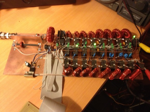
[k3ng] built his own automatic antenna tuner. First, it measures the SWR of the line by using a tandem match coupler. This device allows the forward and reflected signals on the line to be extracted. They are buffered and fed into an Arduino for sampling. Using this data, the device can calculate the SWR. The RF signal is also divided and sampled to measure frequency.

To automate tuning, an Arduino switches a bank of capacitors and inductors in and out of the circuit. By varying the load, it can find the ideal matching for the given antenna and frequency. Once it does, the settings are stored in EEPROM so that they can be recalled later.

After the break, check out a video of the tuner clicking its relays and matching a load.

Continue reading “Automatic Antenna Tuner”

Making A 9GHz Doppler Radar

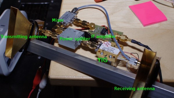
[Kalle] is currently building an FMCW radar, but as he doesn’t have all the parts finished he decided to build a 9GHZ doppler radar in the mean time. The H-plane horn antennas were made from brass sheet and soldered together. [Kalle] checked the matching between the emitter and the antenna by inserting a directional coupler between the two and measuring the intensity of the reflected signal (approximated return loss). At 9Ghz, the Doppler shift for a 1 meter per second speed is about 30Hz so he connected the radar’s output signal to his soundcard.

A quick explanation of the Doppler effect that a radar uses: if you send an RF signal at a given frequency to a moving target, the reflected signal’s frequency will be shifted. It is commonly heard when a vehicle sounding a siren or horn approaches, passes, and recedes from an observer. The received frequency is higher (compared to the emitted frequency) during the approach, it is identical at the instant of passing by, and it is lower during the recession. Hackaday featured plenty of projects using this effect: a small doppler motion sensor, gesture control using doppler shift, hacking an old radar gun

Ask Hackaday: Building Nano Scale Antennas

As an RF engineering student, [Camerin] is usually tasked with pointless yet educational endeavors by his advisor and professors. Most of the time (we hope) he sees the task through and ends up pulling something out of his hat, but a few days ago a professor dropped a bombshell on him. After reading this article on nano scale antenna fabrication, a professor asked [Camerin] if it was possible to build a 3D inkjet printer with a ludicrous amount of accuracy and precision.

The full article, Conformal Printing of Electrically Small Antennas on Three-Dimensional Surfaces, was recently published in Advanced Materials and is available via Google Scholar. The jist of the article is that three-dimensional antennas printed on a sphere approach the physical limits of how good an antenna can be. To test out these small, spherical antennas, the authors of the paper built an extremely high-precision 3D inkjet printer that draws antenna traces on a glass sphere with conductive ink.

The positional accuracy of this printer is 50 nanometers, or about half the size of an HIV virus. The conductive silver ink is delivered by a nozzle with a diameter of 100 to 30 µm and prints onto a glass sphere about 6 mm in diameter. This is a level of precision that companies and research institutions pay top dollar for, so we’re left wondering how the authors built this thing.

We’re turning this question over to the astute readers of Hackaday: how exactly would you build a 3D inkjet printer with this much accuracy and precision? Would it even need to be that precise? Post your answer in the comments.

Tactical Wifi Cantenna Needs Picatinny Rails

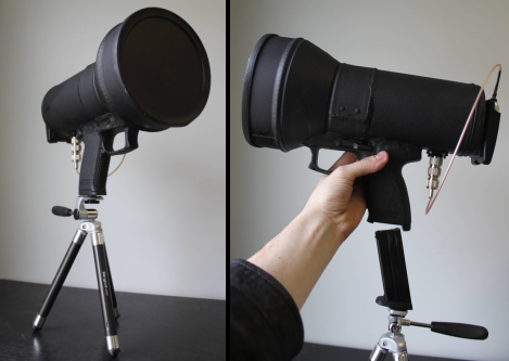
[Wes] built a cool looking Tactical Wifi Cantenna with some parts from a broken airsoft pistol. The antenna is a cookie can type with an added cone to increase performance, as seen in this tutorial. Once the antenna was built it was time to add some kind of handle, [Wes] just so happened to have such a thing on hand. After epoxy puddying the pistol’s grip to his cookie cantenna he observed that the magazine lock was still functioning. Quick thinking and the application of a  hammer in nut allows the whole rig to quickly attach to the tripod. The antenna also sports a plastic lid and textured paint finish for that ultimate tactical look and feel. A USB Alpha AWUSO36H Wifi dongle even mounts on the back of the rig. We wouldn’t go around outside pointing this at stuff attaching and detaching the tripod but the finish looks great, nicely done!

Check out some other various types of cantennas, even a rifle version if you crave more wifi goodness.

EM Brace For Sensing Magnetic Fields


We’ve discussed the notion of using machines to add or improve sensory input to the body before, and we’ve found another project with the same idea. [Nick Hasty] has developed an object he calls the EM Brace, which allows the user to sense electromagnetic fields with a wave of the hand.

The device works by connecting two antennas to an enclosure that contains a speaker. The enclosure is intended to be worn on the back with a harness securing it in place and wrapping the arms around the wearer’s body. The antennas are incorporated into a pair of gloves. When the antennas pick up electromagnetic radiation, the speaker emits a low frequency sound waves. They vibrate the enclosure and the arms, which in turn vibrate the body, signaling to the wearer that he or she is in an electromagnetic field, also referred to as hertzian space. A good deal of detail about the project can be found on his blog, or if you prefer, download his thesis paper in(PDF).

[via Make]