To prevent data corruption when using multiple SPI devices on the same bus, care must be taken to ensure that they are only accessed from within the main loop, or from the interrupt routine, never both. Data corruption can happen when one device is chip selected in the main loop, and then during that transfer an interrupt occurs, chip selecting another device. The original device now gets incorrect data.
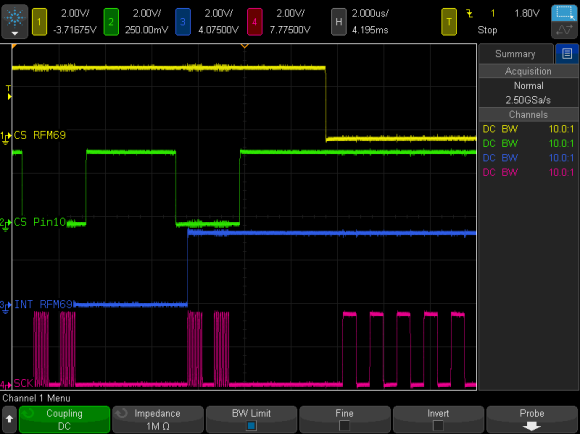
For the last several weeks, [Paul] has been working on a new Arduino SPI library, to solve these types of conflicts. In the above scenario, the new library will generate a blocking SPI transaction, thus allowing the first main loop SPI transfer to complete, before attempting the second transfer. This is illustrated in the picture above, the blue trace rising edge is when the interrupt occurred, during the green trace chip select. The best part, it only affects SPI, your other interrupts will still happen on time. No servo jitter!
This is just one of the new library features, check out the link above for the rest. [Paul] sums it up best: “protects your SPI access from other interrupt-based libraries, and guarantees correct setting while you use the SPI bus”.
 For [Tony]’s entry for The Hackaday Prize,