We Salute The Television Tube Flag

From [Gijs] comes Beeldbuis Vlag Tijsdlijn, or television tube flag (Translated). We’re not up on our Dutch, but it appears that [Gijs] and friends have created a television tube which waves much like a flag in response to airflow from a fan.  The effect is pretty darn amazing, and that’s putting it mildly. To create this hack, [Gijs] built a modified Wobbulator. The Wobbulator is an early video synthesizer which used added steering coils to modify the operation of a standard TV tube. When excited, the coils would deflect the tube’s electron beam, causing some rather trippy images to appear on-screen. (Yes, here at Hackaday “trippy” is a scientific term).

[Gijs] wanted his screen to be “waved” by a fan, just like a flag would wave. To do this he used an anemometer made of ping-pong ball halves. The anemometer spins up a DC motor from a CD-ROM drive. In this application, the motor acts as a generator, creating a DC voltage. An ATmega328 running the Arduino code reads the voltage from the motor. If the anemometer is spinning, the Arduino then outputs a sinusoidal value. The Arduino’s output is amplified and applied to the coil on the CRT. A network of power resistors ensures the amplifier is correctly loaded. The results speak for themselves. In the video after the break, the tube flag is displaying a slide show of photographs of its construction. As an added hack, [Gijs] used an Arduino Leonardo as a USB keyboard. When the anemometer spins, the primary ATmega328 sends a signal to the Leonardo, which then emulates a push of the arrow keys on the host computer. This lets the tube flag advance its own images. Very cool work indeed!

Continue reading “We Salute The Television Tube Flag”

LuxBlaster: Blast A Beam Of Light At The Most Intense Light Source

HighBeams

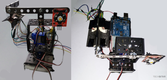
[Hazim] wrote in to tell us about his project that teaches inconsiderate drivers a lesson! Well, theoretically. The LuxBlaster is a spot light which points towards the most intense light source.

The idea is that you can blast drivers who do not turn their high-beams off with a reverse high-beam of your own. It is very important to note that this should never be used, as [Hazim] also clearly states. While this project is meant to prove that it can be done (a “what if”) project, it has two components that are very well done and can easily be used in different projects: the Arduino controlled spotlight and the light intensity tracker.

What would you use an Arduino controlled spotlight for? Smart lighting? What about a light source tracker? Let us know in the comments.

Continue reading “LuxBlaster: Blast A Beam Of Light At The Most Intense Light Source”

An Arduino Programmable Load

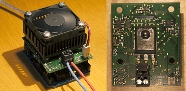
Having a big block of hot to dump current into is a very useful thing to have if you’re testing batteries, power supplies, high power LEDs, electroplating, or any thing else that would normally require a huge resistor. [Jakub] found himself in need of an electronic load, and instead of a transistor and a pot, decided to make something more automatic: a programmable load built around an Arduino shield.

The idea behind this load is pretty simple: connect a device to a FET and shunt resistor to measure current. Drive the gate of the FET with an op-amp that maintains either constant current or constant voltage. Control everything with a DAC, and you have a programmable load controlled by an Arduino.

With such a small form factor, getting rid of all that heat was bound to be a problem. For this, [Jakub] is using a 50×50 mm BGA style heat sink with a 5V fan. If it’s good enough for a big CPU, it should be able to handle dumping 70 Watts into a FET. There’s also a conservative application of thermal paste and a very small thermistor underneath the FET that’s able to be read by the Arduino. It might slowly heat up your room, but it’s not going to catch fire.

With the Arduino sketches [Jakub] wrote for his load he was able to characterize a pair of Idea batteries and figure out how much charge a three-year-old recyclable battery had. It’s a great piece of work, and if [Jakub] is willing to go through the hassle of a Kickstarter, it would make a fine crowdfunded product.

Arduino Gets Fowl With Flappy Bit

flappy-bit

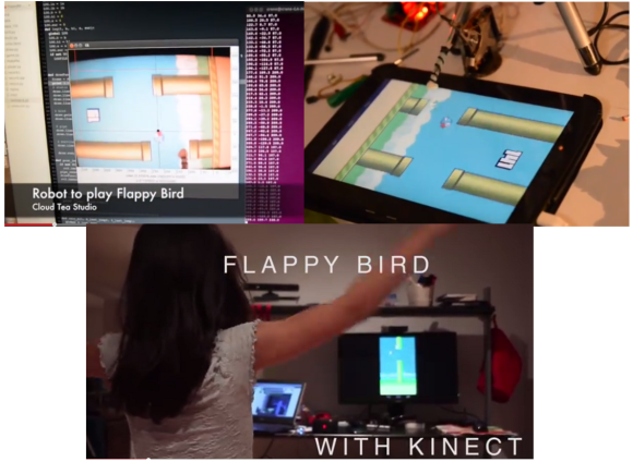
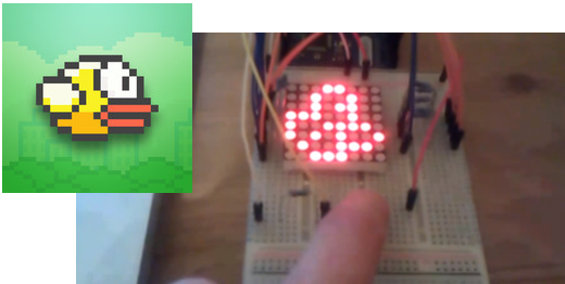
We have to swallow our pride and hand it to [Dan200]. He may have finally found an application that everyone can agree is a perfect fit for Arduino. Flappy Bit is [Dan’s] Arduino Uno based Flappy Bird clone. [Dan] is a software guy at heart, but he’s taken a peck at electronics of late. Flappy Bit was just a fun side project for him to learn how to program the Arduino. The hardware consists of an 8×8 LED matrix, current limiting resistors, and a single button.

[Dan’s] implementation isn’t 100% faithful to the iOS/Android original. Rather than simply parrot Flappy Bird, he changed it up a bit. The user presses and holds the button to climb, and releases it to descend. This seems to make the game a bit more forgiving. We also won’t be missing all the lovely sound effects from Flappy Bird.  While there is less flapping in Flappy Bit, it does make us more nostalgic for those  tabletop LCD/LED games we played in the 80’s and can’t stop crowing about today.

[Dan] has released the full source code to the project (Pastebin link), and there is more information available on his reddit thread. Give flappy bit a try. You won’t egret it!

Continue reading “Arduino Gets Fowl With Flappy Bit”

STM32 Nucleo, The Mbed-Enabled, Arduino-Compatable Board

The STM32 line of microcontrollers – usually seen in the form of an ST Discovery dev board – are amazingly powerful and very popular micros seen in projects with some very hefty processing and memory requirements. Now, ST has released a great way to try out the STM32 line with the Nucleo board.

There are two really great features about these new Nucleo boards. First, they’re mbed compatable, making them a great way to get started in the ARM development world. Secondly, they have Arduino pin headers right on the board, giving you access to all your shields right out of the box.

Right now, there are four varieties of the Nucleo board based on the STM32F030, -F103, -F152, and -F401 microcontrollers. The STM32F401 is the high-powered variant, An ARM Cortex-M4 microcontroller running at 84 MHz, 512kB of Flash, and enough I/O for just about any project.

If you’d like to get your hands on one of the STM32 Nucleo boards, you can order a voucher to pick one up at Embedded World in Germany next week. Otherwise, you’re stuck ordering from Mouser or Farnell. Bonus: the high-end F401-based board is only $10 USD.

Make Your Own Smart Watch

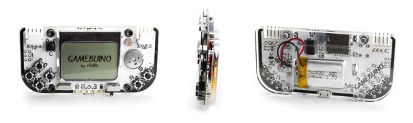
Wearables are all the rage lately. Have you been eyeing the Pebble or one of the new smart watches lately but are not sure if it’s for you? With [GodsTale’s] “Retro Watch” you can now build your own, allowing you to try out a smart watch without making a huge investment.

This smart watch uses very common and easy to obtain parts: Arduino Pro Mini, HC-06 Bluetooth module, Adafruit’s 0.96’’ OLED display, and a lithium battery. It is amazing how few parts can be used to make such a functional project. While the example packaging shown is a bit rugged around the edges, it gets the job done. Having such simple hardware allows [GodsTale] to focus on the software. One of the coolest aspects of this project is the Android app [GodsTale] provides. The app provides basic functionality, such as viewing RSS feeds and Android notifications. Check out the GitHub and a more detailed write-up for more information.

It would be great to see this project evolve in the future, it has so much potential. We would love to see a custom circuit board, or a model for a 3D printed case for this awesome smart watch. See a video of the Retro Watch in action after the break. If you thought this was cool, check out a few of these recent hacks.

Continue reading “Make Your Own Smart Watch”

Nrf24l01+ Using 3 ATtiny85 Pins

[Ralph] wasn’t satisfied with the required 5 control pins to drive his nrf24l01+ transceiver module, so he used this circuit needing just 3 pin using an ATtiny85.

One of the key components was to effectively drive the chip select (CSN) line from the clock (SCK) line. The nrf24l01+ needs the CSN line to transition from high to low on the beginning of a communication.  [Ralph] put the SCK line behind a diode, put a capacitor in parallel with the CSN line and altered the arduino-nrf24l01 library to encode extra delays for the clock line.  This allowed the CSN line to be driven by the SCK line. Subsequent line transitions during transmission happen too fast to charge the capacitor, leaving the CSN line in a low state.

After tying the chip enable line high and dropping the 5V power line to 1.9-3.6V across a red LED, [Ralph] had an ATtiny85 controlling a nrf24l01+ module.

Though deceptively simple, a very cool hack that opens up a couple more lines on the ATtiny85.