AVR Fuse Bits Explained

Every AVR microcontroller, from the ATtiny in your thermostat to the ATMega in your Arduino, stores its configuration in a series of fuse bits. These fuse bits control settings such as the multiplier of the internal oscillator (and thus the speed of the chip), or if the reset pin can be used as a GPIO pin. [YS] just put up an awesome tutorial for understanding these fuse/lock bits, and it’s just the reference guide you’ll need when you find your AVR is running 8 times slower than you would like.

As an example, [YS] uses the ATMega48 default settings. From the factory, the ‘Mega48 ships with it’s fuse bits set to use an 8MHz internal RC oscillator with the CKDIV8 bit set. This results in the chip operating at 1MHz, a bit slow for [YS]’ liking.

By looking at the datasheet for the ATMega48, [YS] found the CKDIV8 fuse was the 7th bit in the low fuse byte. From the factory, the default value for this byte is 0b01100010. To remove the ‘divide clock by 8’ bit, [YS] needed to change the low byte to 0b11100010, or 0xE2. This is done via AVRdude by appending lfuse:w:0xE2:m to the commands entered when programming.

Fuse bits don’t need to be scary. As long as you can convert between binary and hex, can remember there are 7 bits in a byte (remember to start counting from 0), and have access to an easy to use fuse calculator, it’s possible to change all the settings on any AVR you have on hand.


Arduino Voltage Measurement Tricks

We think it’s a great learning experience to tear back the veil of abstraction and learn a bit more about the hardware found on an Arduino board. This project is a great example. [Scott Daniels] takes a look at the other voltage measurement options available to AVR chips used by Arduino.

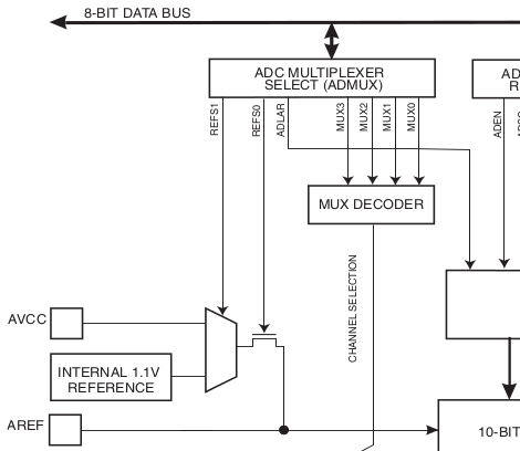
If you’ve used the analogRead() function then you’ve already measured a voltage using the Arduino. But do you know what is going on behind the scenes to make this happen? The Analog to Digital converter on the AVR chip is being used to measure an incoming voltage by comparing it to a known voltage reference. That reference is by default the supply voltage line for the chip. This should be 5V but will only be as accurate as the regulator supplying it. [Scott] looks at the other voltage references that may be used. An external reference can be used by adding hardware, but that’s not the focus of his article. Instead he looks at using the 1.1V internal reference. He’s written some short example code that let’s you measure the incoming line voltage based on that internal reference. This is a very handy trick that can let you detect when the chips is running from a battery and how much juice is left in the cell.

Toorcamp: Bliplace 2.0

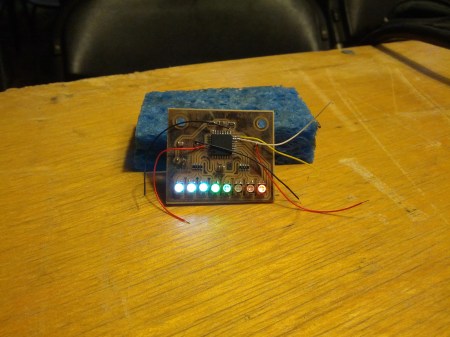
We’ve shown [Tanjent]’s Bliplace 1.0 in the past. He handed out a few hundred of the open source audio toys at Burning Man. At Toorcamp, he’s been showing off an improved 2.0 version of the project. This one has a more powerful microcontroller and many more RGB LEDs.

The device uses the ATMega328 and an electret microphone to sample ambient noise. It the processes the sound into a light pattern which is displayed on the line of RGB LEDs. The demo that I saw showed the LEDs synchronized to bass frequencies, which it could pick up at a range from the large sub-woofers at Toorcamp. It’s powered by a CR2032 coin cell battery, which means it can be worn as a neat audio toy.

This prototype version was etched in his kitchen but [Tanjent] is working on making a production version of the PCB. He plans to release it as a surface mount soldering kit.

A Detailed Tutorial On Speeding Up AVR Division

[Alan Burlison] is working on an Arduino project with an accelerometer and a few LEDs. Having the LEDs light up as his board is tilted to one side or another is an easy enough project a computer cowboy could whip out in an hour, but [Alan] – ever the perfectionist – decided to optimize his code so his accelerometer-controlled LEDs don’t jitter. The result is a spectacular blog post chronicling the pitfalls of floating point math and division on an AVR.

To remove the jitter from his LEDs, [Alan] used a smoothing algorithm known as an exponential moving average. This algorithm uses multiplication and is usually implemented using floating point arithmetic. Unfortunately, AVRs don’t have floating point arithmetic so [Alan] used fixed point arithmetic – a system similar to balancing your checkbook in cents rather than dollars.

With a clever use of bit shifting to calculate the average with scaling, [Alan] was able to make the fixed point version nearly six times faster than  the floating point algorithm implementation. After digging into the assembly of his fixed point algorithm, he was able to speed it up to 10 times faster than floating point arithmetic.

The takeaway from [Alan]’s adventures in arithmetic is that division on an AVR is slow. Not very surprising after you realize the AVR doesn’t have a division instruction. Of course, sometimes you can’t get around having to divide so multiplying by the reciprocal and using fixed point arithmetic is the way to go if speed is an issue.

Sure, squeezing every last cycle out of an 8 bit microcontroller is a bit excessive if you’re just using an Arduino as a switch. If you’re doing something with graphics or need very fast response times, [Alan] gives a lot of really useful tips.

The Effect Of Code On Power Consumption

Of course putting a microcontroller into sleep mode or changing the clock rate has an effect on the power consumption of the chip, but what about different bits of code? Is multiplying two numbers more efficient than adding them, and does ORing two values consume more power than NOPping? [jcw] wanted to compare the power draw of a microcontroller running different loops, so he threw some code on a JeeNode and hooked it up to an oscilloscope.

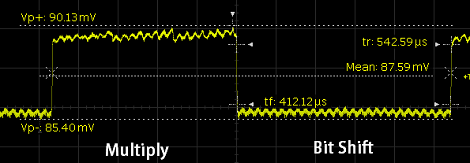
For his test, [jcw] tested two instructions: multiply and shift left. These loops run 50,000 and 5,000 times, respectively (bit shifting is really slow on ATMegas, apparently) and looked at the oscilloscope as the JeeNode was doing its work.

Surprisingly, there is a difference in power consumption between the multiply and shift loops. The shift loop draws 8.4 mA, while the multiply loop draws 8.8 mA. Not much, but clearly visible and measurable. While you’re probably not going to optimize the power draw of a project by only using low-power instructions, it’s still very interesting to watch a microcontroller do its thing.

ATtiny85 Sketch Flashing Rig

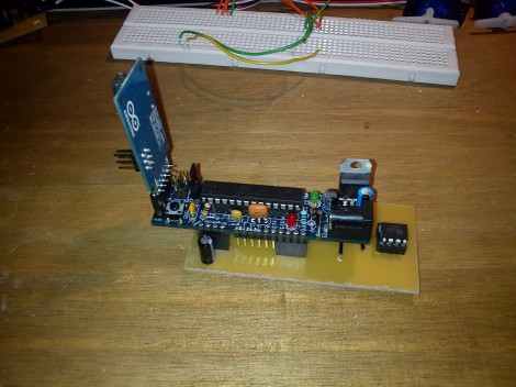
We’re happy to see Arduino enthusiasts championing the use of smaller hardware when the need for a full-blown ATmega-based board just isn’t there. [Chris] has been doing just that, using ATtiny85 chips in his projects. But he’s tired of hooking jumper wires to flash the sketches. He finally got around to etching this ATtiny85 programming adapter.

If the project is not pin hungry, an ATtiny85 can run Arduino sketches without the need to port the code. The best news is that the Arduino board you used to prototype the project can be used as the programmer for the standalone chip. Here that’s a Boarduino, and [Chris] laid out a double row of female pin headers for quick plug-in. To the right you can see the DIP socket for the target chip. Although this works perfectly well, we would have liked to also see the inclusion of a 2×3 AVR ISP programming header which could be used with the full range of AT chips.

One Wire Reads The Keypad From The APRS Radio Mic

[Shane Burrell] decided to spend some time learning how the keypad on the his Kenwood TM-710A APRS radio mic works. It uses a different technique than you might think. Normally a grid of buttons is scanned as a matrix to detect keypresses, but this hardware actually counts pulses on a serial wire to take each reading.

The stock radio sends a steady digital pulse to the handset and with each pulse the mic pulls the line low. It then uses a 4017 decade counter to see what comes back. If the edge count matches it means nothing is pressed, but a change in the number of pulses returning to the base unit can be used to extrapolate which button has been pressed.

[Shane] went on to implement this control technique using an AVR chip in place of the  radio base unit. He used the data gained from measuring the pulse behavior using an oscilloscope to write the firmware for the project. He filmed a bit of a demo after the break which shows his findings.

We’re not quite sure how this would translate into your own home-brew projects, but the thought of scanning a keypad with two pins of a uC is quite desirable. Sure there is the 555-timer frequency technique, but we’re always down with new ideas.

Continue reading “One Wire Reads The Keypad From The APRS Radio Mic”