Here’s an interesting tip that can help improve your ability to write assembly code. In an effort to remove the complexity of assembly code for an AVR project [Quinn Dunki] figured out how to use macros when writing AVR code with the GNU toolchain. Anyone using AVR-GCC should keep this in mind if they ever want or need to pound out a project in assembly language.
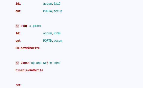
If you look at the code snippet above you’ll see two commands that are obviously not assembly; PulseVRAMWrite and DisableVRAMWrite. These are macros that direct the assembler to roll in a hunk of code. But avr-as, the assembler used with this toolchain, lacks the ability to handle macros. That’s too bad because we agree with [Quinn] that these macros make the code easier to read and greatly reduce the probability of error from a typo since the code in the macro will be used repeatedly.
The answer is to alter the makefile to use GNU M4. We hadn’t heard of it, but sure enough it’s already installed on our Linux Mint system (“man m4” for more info). It’s a robust macro processor that swaps out all of her macros based on a separate file which defines them. The result is an assembly file that will play nicely with avr-as.
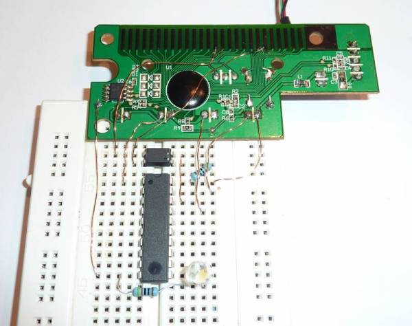
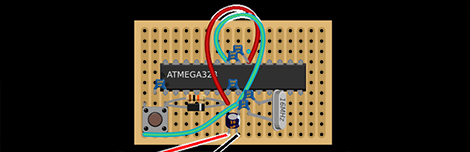
Her implementation is to help in development of the GPU for her Veronica computer project.