DIY Circuit Etching Video Tutorial

toner-paper

Circuit-bending blog GetLoFi has posted the best tutorial yet on home-made printed circuit boards using the toner transfer method.

We’ve covered homebrew PCB fabrication techniques about a billion times before. What sets this tutorial apart is that it collects many bits of knowledge otherwise scattered all about the web, and then depicts the entire process on video, from initial printing to cut PCB…because reading about it versus seeing it done are two different things entirely. They give a number of immensely useful tips throughout: choice of materials and where to get them, tools and techniques, and dispelling several myths about these methods (for example, they’re adamant about not using acetone to clean toner from the PCB). Well worth the 30 minutes to watch. If that’s too much and you’ve been stuck on just one part of the process, the tutorial is in three segments.

Trimming finished boards on a paper cutter? Who would’ve guessed?

[via Make]

PCB Toner Transfer With Dowel

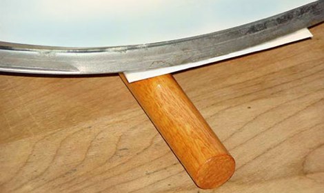
Pulsar Professional FX has a neat tip on their site for getting a really even toner transfer when making your own PCBs. First, the PCB is cut to size, and the paper is tacked to the board. Then, the PCB is placed paper up onto a dowel and rolled back and forth with the iron. Since the board bends slightly over the dowel the toner sticks evenly to the copper. After that, just remove the paper as usual and etch with your preferred method.

Etch PCBs With Ferric Chloride And A Sponge

F7Z9JTTFX23V5VV

Etching a printed circuit board generally takes a bit of time and uses a lot of etchant. [TechShopJim] posted a method that uses a sponge to reduce the amount of etchant used while speeding up the entire process. First, a resist is applied using either a sharpie or the toner transfer method. Using gloves to handle everything, he soaked a sponge in ferric chloride and continually wiped a copper-clad board until all the exposed copper was removed. This technique moves the etchant around more, keeping “fresh” etchant closer to the copper. If you can’t procure ferric chloride, you can also use our method that uses 2 household chemicals: hydrogen peroxide and hydrochloric acid.

Printing Circuits On The RepRap

reprappcb

[Rhys Jones] has been working with the RepRap team to develop a way to print circuit boards. The machine first prints the plastic substrate with channels for the metal to be deposited into. They adapted their pinch wheel feeder to work with solid core solder (flux creates a mess). The extruded solder’s specific heat isn’t hot enough to melt the plastic. They made a video (embedded below) of their test piece: an optical endstop. The team has also been experimenting with decoupling the feed mechanism from the extruder.

Continue reading “Printing Circuits On The RepRap”

How-To: Etch A Single Sided PCB

Making a PCB is very simple; it does not consume a lot of time and the results look professional. After reading this How-To and watching the step by step video, you will be able to make your own PCB in your workshop using just a few inexpensive materials.

Many people use protoboard and point-to-point wire everything, but needing multiple copies of the same circuit is the reason that forces many away from using protoboard. After making your first circuit board, you might not point-to-point wire anything again!

Continue reading “How-To: Etch A Single Sided PCB”

High Power LED Blinking Circuit

[youtube=http://www.youtube.com/watch?v=mNDu56oGNck]
Evil Mad Scientist Labs brings us this easy to make LED blinking circuit. The idea is to put a LED in series with a small blinking incandescent bulb from a string of Christmas lights. The bulb has an internal bimetallic strip that bends out of shape when it heats up, cutting the circuit. when it cools enough, it returns to its original shape and closes the circuit again, making the bulb and the LED turn on. Both lights have short period of sustained light when they are initially powered up since the bimetallic strip is still warming up.

The project uses a 5W blue LED, the aforementioned bulb, and a 6V battery pack loaded with 3 AAA batteries. The battery pack and the lights are all attached to a small section of perforated board. Duplicating this project should be easy and provide a very bright LED, but to make a 5W LED shine its brightest, a larger bulb and a heatsink will be necessary.

Notacon 2008: Circuit Bending Will Get You Laid


[Pete Edwards] and [Fred Owsley] openly admitted that the title was the most thinly veiled audience-bait ever constructed. Nevertheless, they poured through a great talk covering the basics of circuit bending and some of the pieces they had built over the years. Fred said that what attracts him to circuit bending is the hands on approach to something very scientific i.e. he can figure out how to construct an interesting circuit by rubbing his finger along the back of the board. As far as where to start: always a battery powered device and use the toy store as a last resort. You’re going to tear the thing apart so why pay for it? Dumpster diving, garage sales, swap meets, and flea markets are all places to look. Parts don’t need to be anything better than grab bag either. They suggested an easy first step is dropping the operating voltage of your device and seeing how it reacts. Pete and Fred had several examples of devices they’ve modified: Speak & Spells, Casio SA keyboards, Barbi karaoke machines, and the voice changing gas mask pictured above.

The Bent Festival for circuit bending is coming up soon if you’d like to see more. You can also check out these links for more information on circuit bending.