One of the major difficulties in studying electricity, especially when compared to many other physical phenomena, is that it cannot be observed directly by human senses. We can manipulate it to perform various tasks and see its effects indirectly, like the ionized channels formed during lightning strikes or the resistive heating of objects, but its underlying behavior is largely hidden from view. Even mathematical descriptions can quickly become complex and counter-intuitive, obscured behind layers of math and theory. Still, [lcamtuf] has made some strides in demystifying aspects of electricity in this introduction to analog filters.
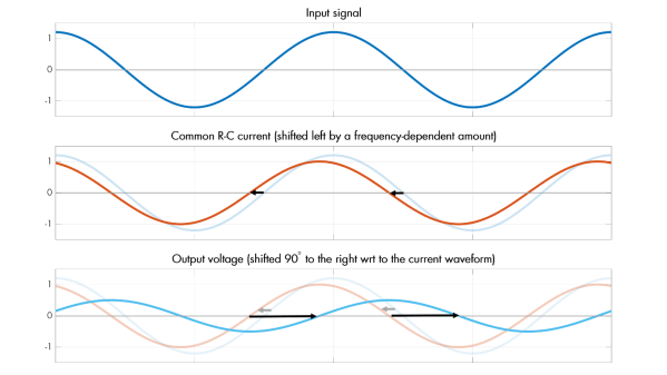
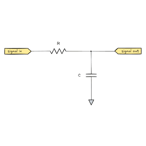 The discussion on analog filters looks at a few straightforward examples first. Starting with an resistor-capacitor (RC) filter, [lcamtuf] explains it by breaking its behavior down into steps of how the circuit behaves over time. Starting with a DC source and no load, and then removing the resistor to show just the behavior of a capacitor, shows the basics of this circuit from various perspectives. From there it moves into how it behaves when exposed to a sine wave instead of a DC source, which is key to understanding its behavior in arbitrary analog environments such as those involved in audio applications.
There’s some math underlying all of these explanations, of course, but it’s not overwhelming like a third-year electrical engineering course might be. For anyone looking to get into signal processing or even just building a really nice set of speakers for their home theater, this is an excellent primer. We’ve seen some other demonstrations of filtering data as well, like this one which demonstrates basic filtering using a microcontroller.
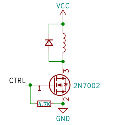 Perhaps, that’s the single most popular use for an NPN transistor – driving coils, like relays or solenoids. We are quite used to driving relays with BJTs, typically an NPN – but it doesn’t have to be a BJT, FETs often will do the job just as fine! Here’s an N-FET, used in the exact same configuration as a typical BJT is, except instead of a base current limiting resistor, we have a gate-source resistor – you can’t quite solder the BJT out and solder the FET in after you have designed the board, but it’s a pretty seamless replacement otherwise. The freewheel (back EMF protection) diode is still needed for when you switch the relay and the coil produces wacky voltages in protest, but hey, can’t have every single aspect be superior.